Development of custom electronic boards with CNC Router.
Your project should incorporate:
I am very excited about my final project, where I will use SolidWorks software to design in both 2D and 3D. This project will be an integration of multiple manufacturing processes, which will be detailed step by step. I'm looking forward to diving into designing and creating something tangible through this powerful and versatile software.
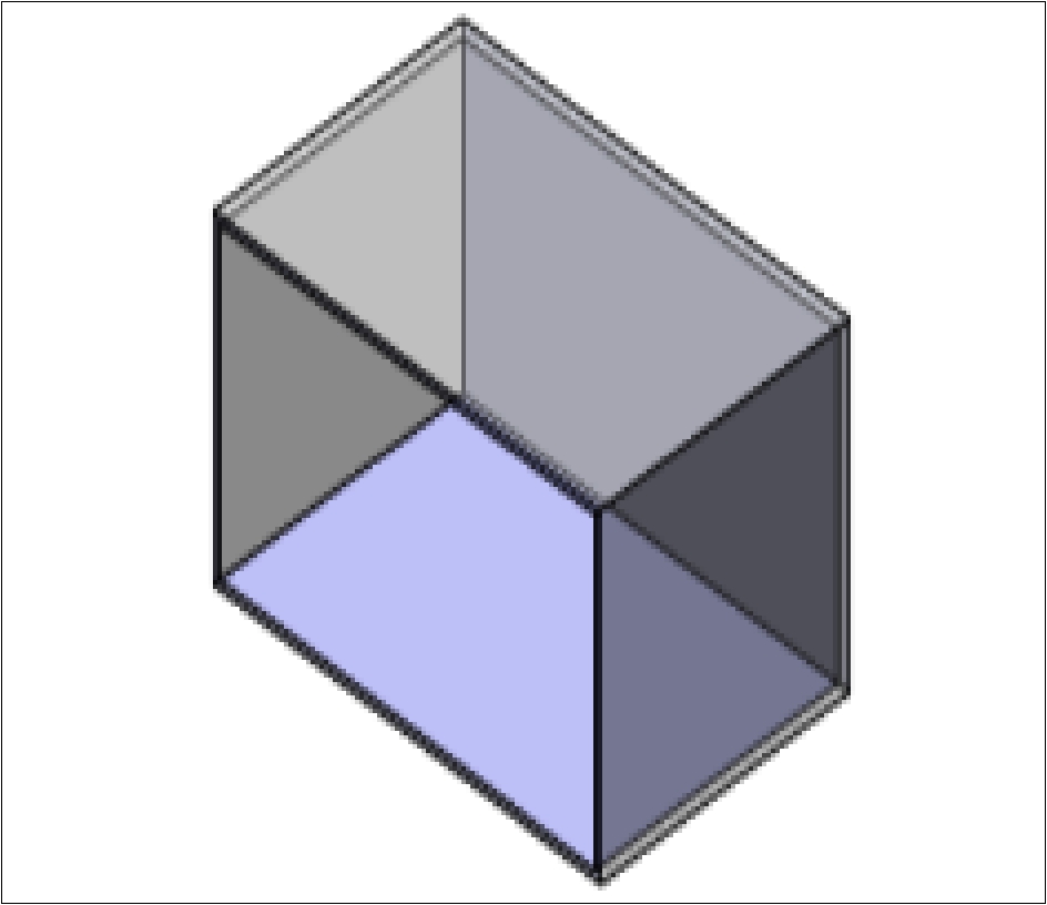
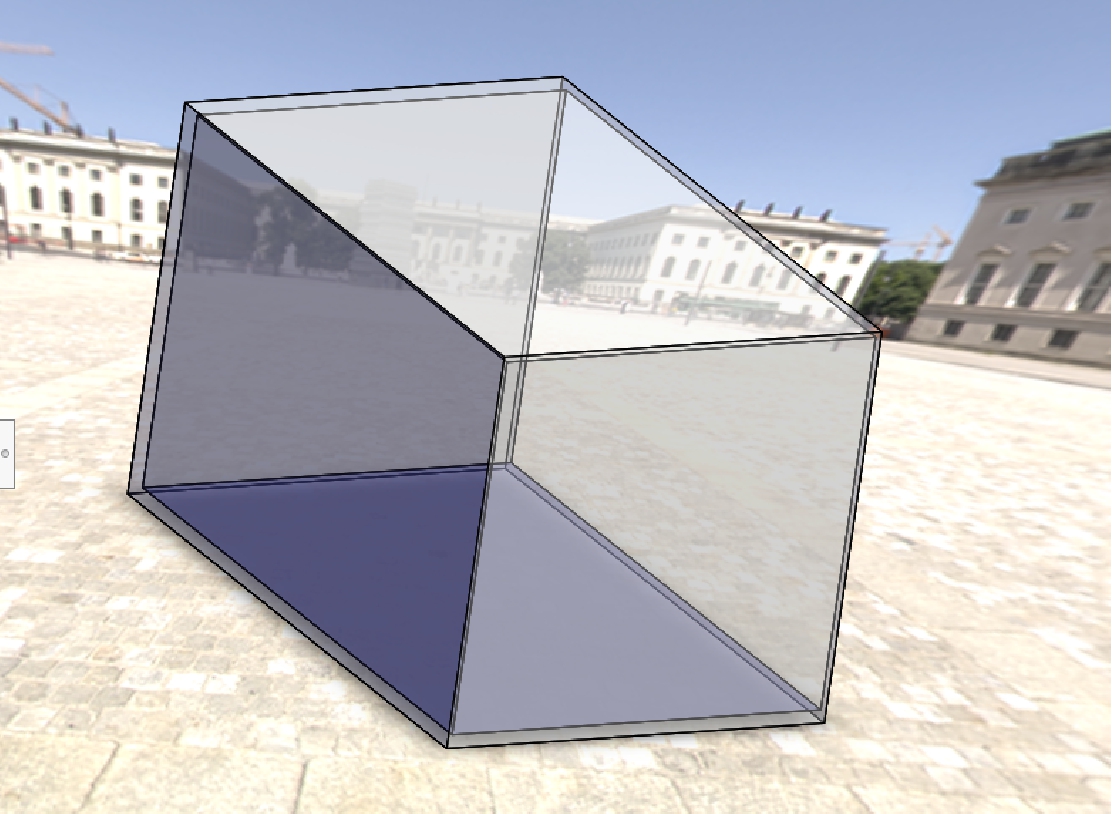
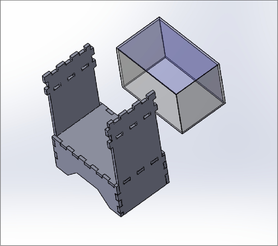
During the last few days, my attention has been completely focused on the meticulous design of the essential elements for the completion of my project: the case and the glass in the SolidWorks software since it is an important part because it will be the visual part of the project.
A glass tank or container was considered to be able to contrast whether the parameters that I see on the cell phones or application are true or not, and the measurements come below.
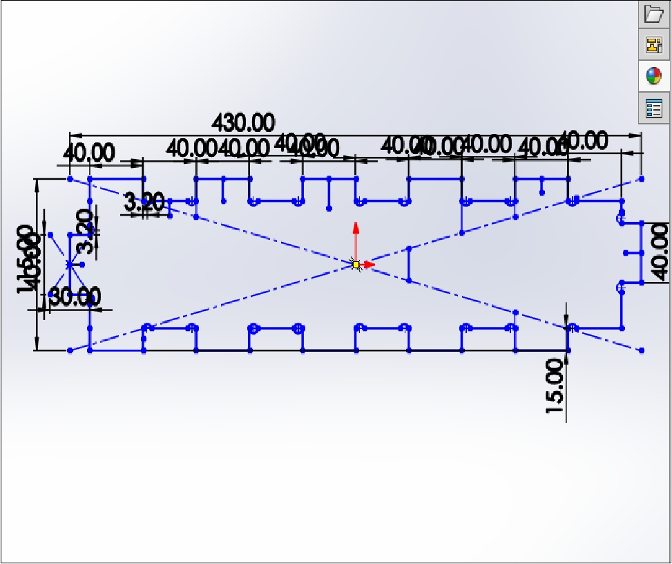
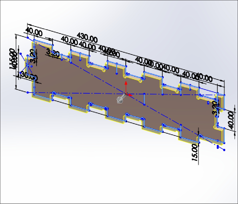
These pieces are the supports of the project, which will be built with OSB material.
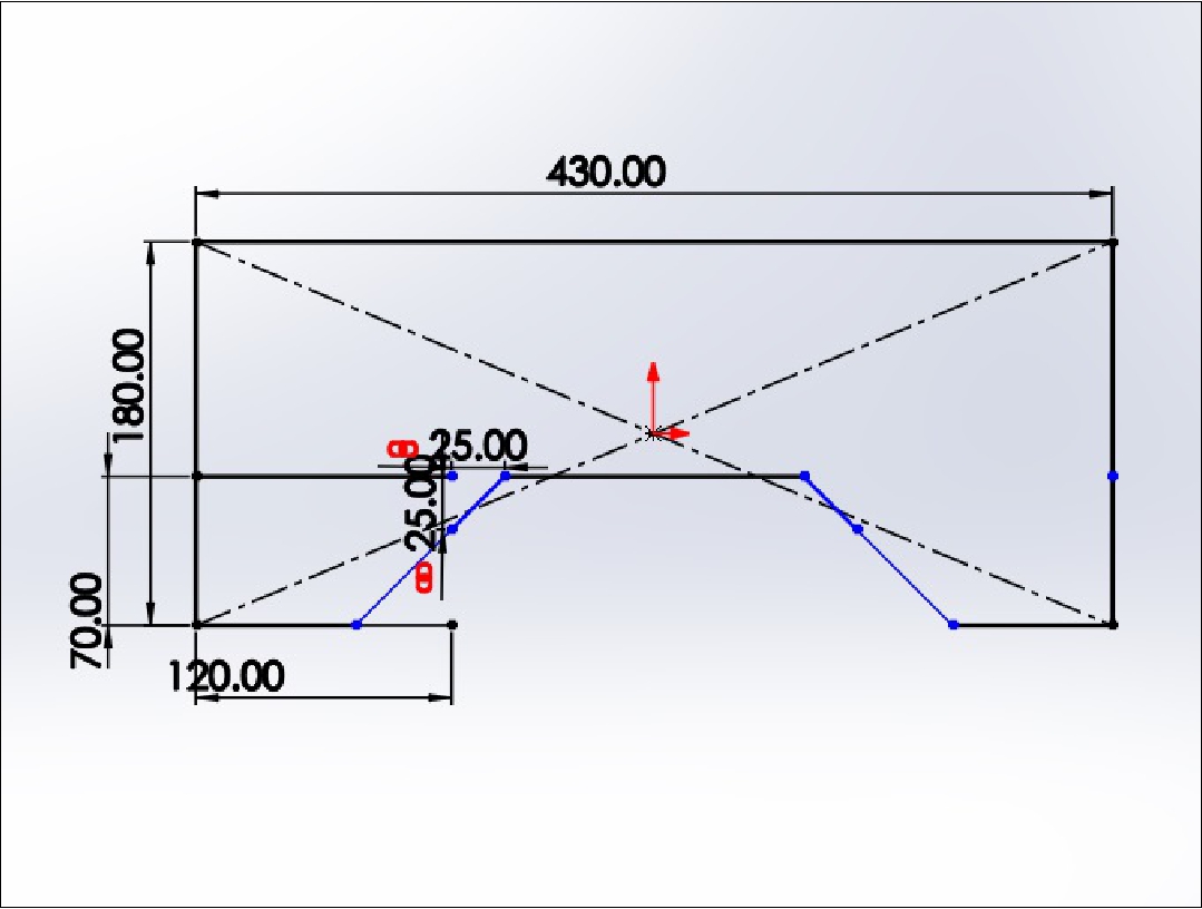
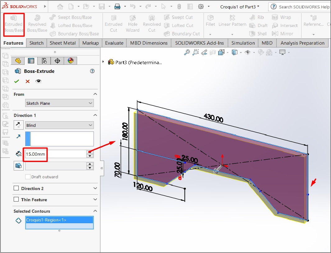
The third piece corresponds to the side supports of the project, which are also made of 15 mm thick OSB.
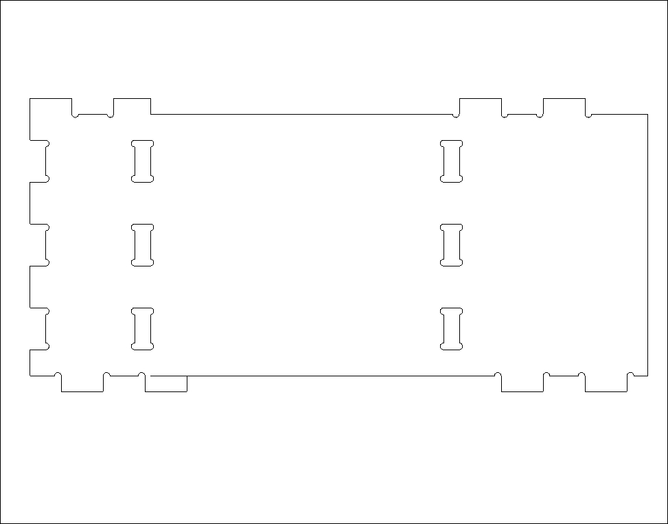
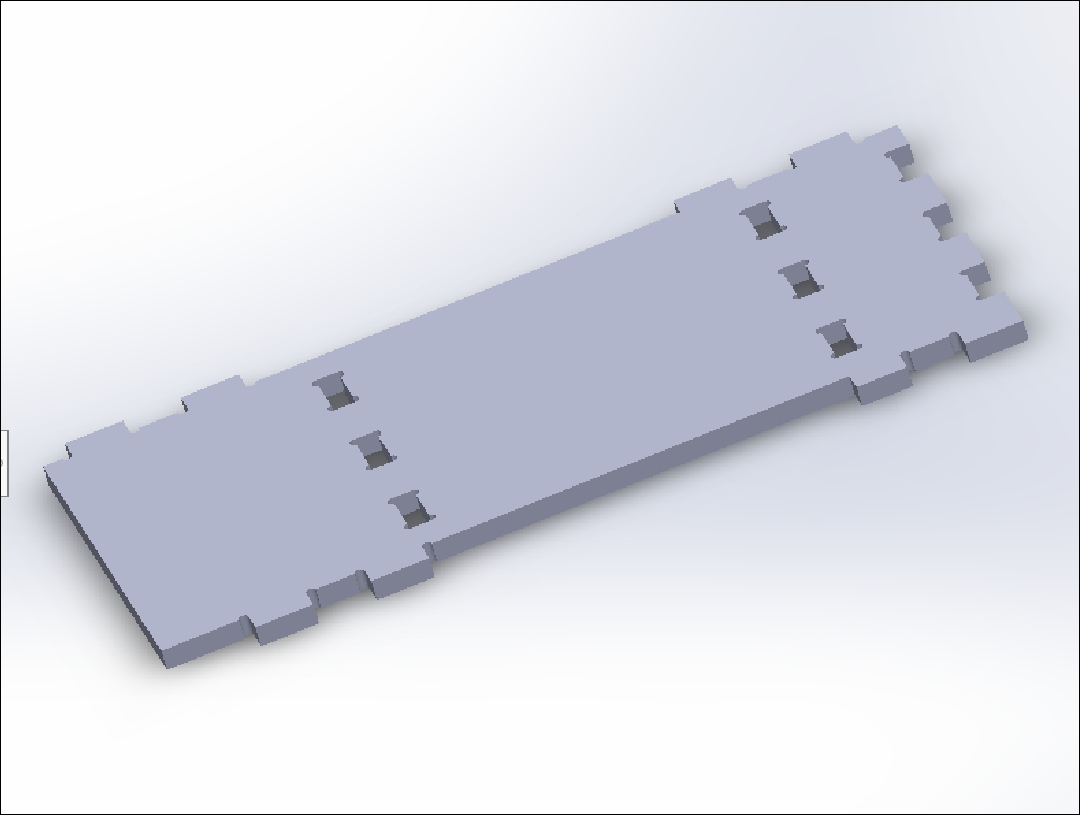
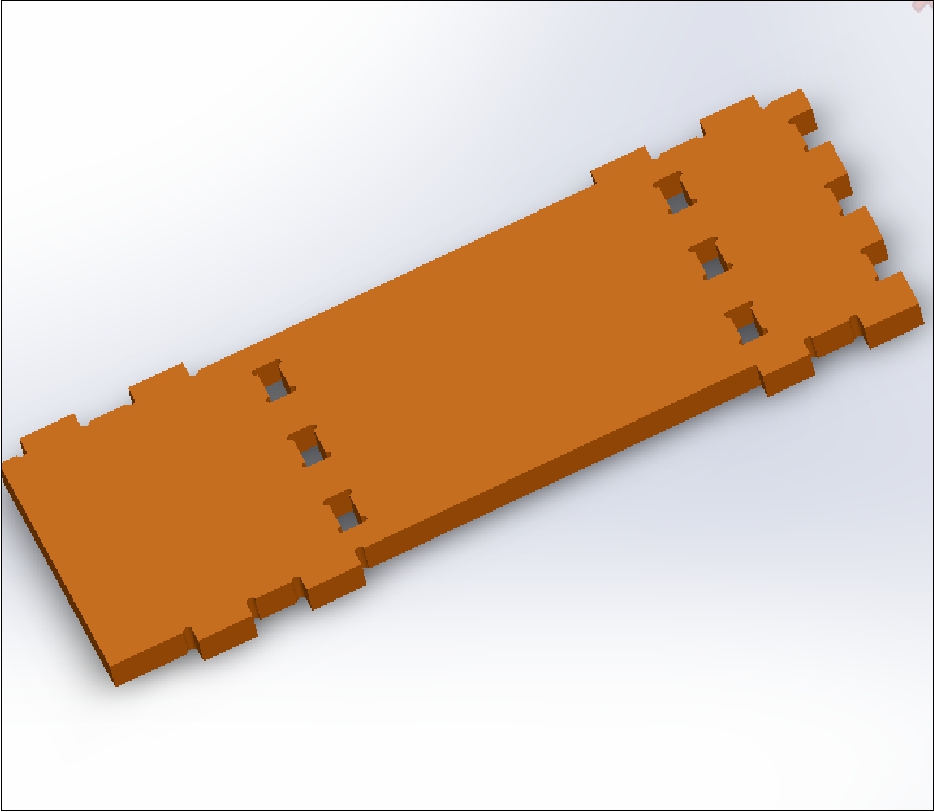
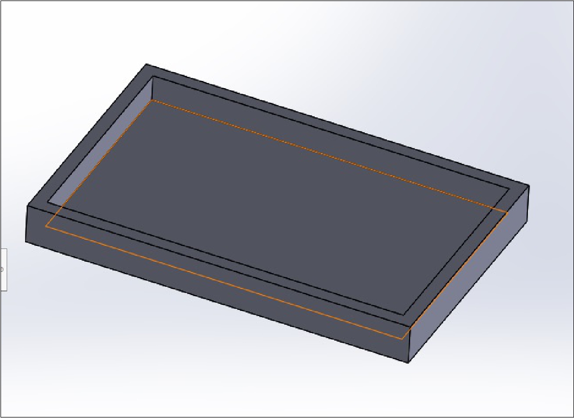
The fourth piece is the platform or table on which the container with water will be placed, which will also be made of 15 mm thick OSB. It is also the top cover of the project
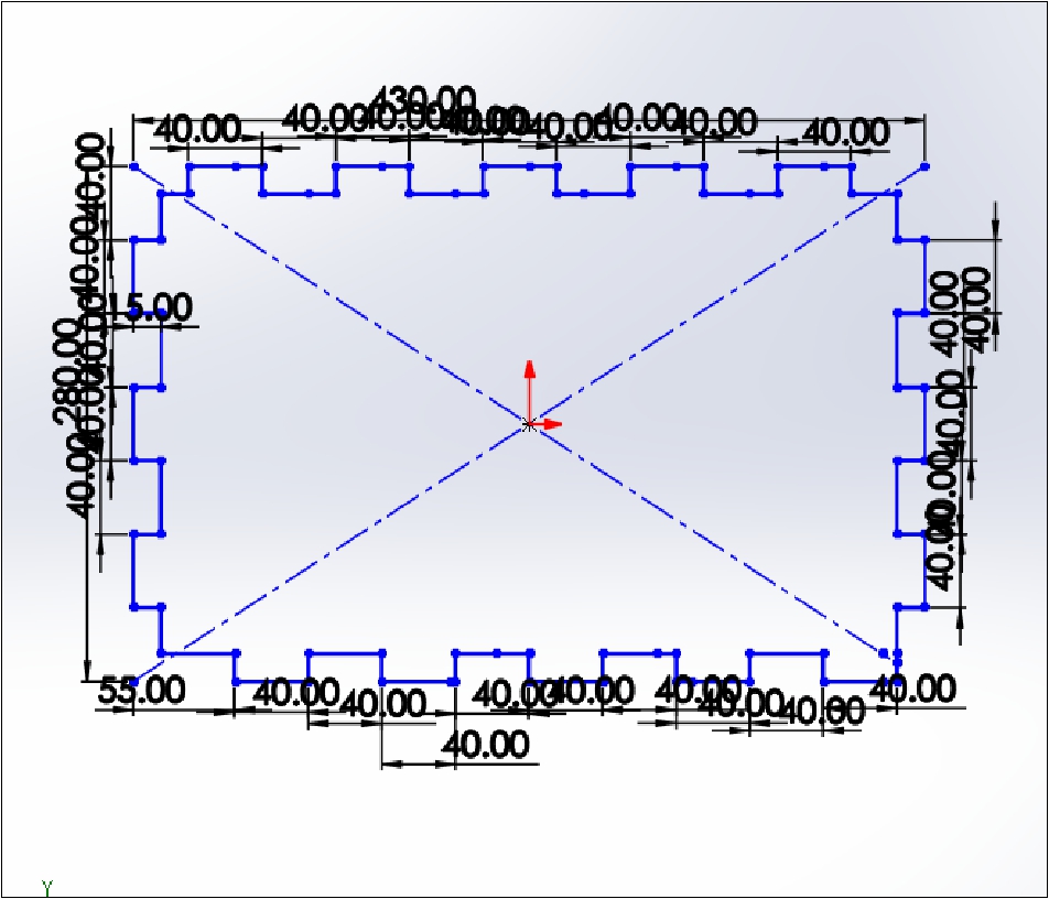
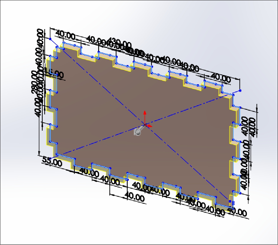
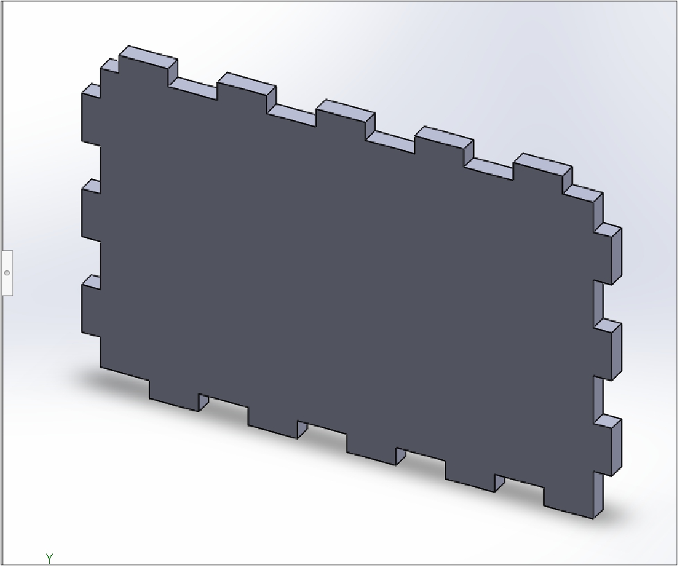
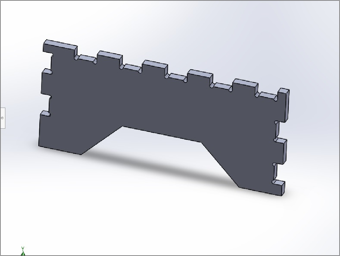
The fifth piece acts as a support and cover for the electronic part that will be placed on top.
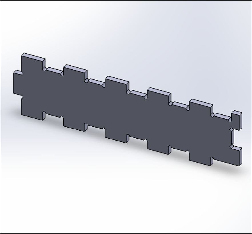
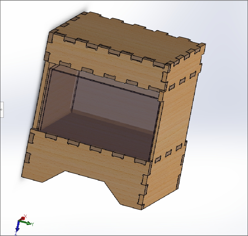
This image illustrates part of the final appearance of the 3D project designed in the software SolidWorks.
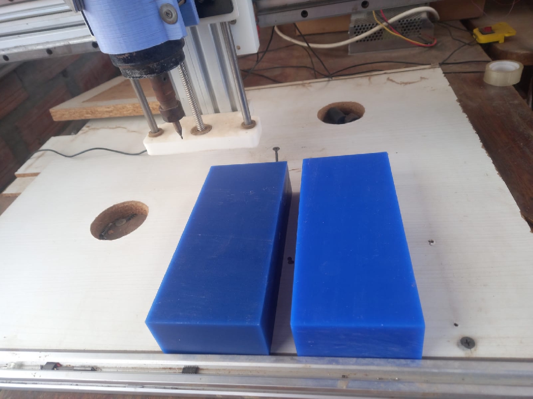
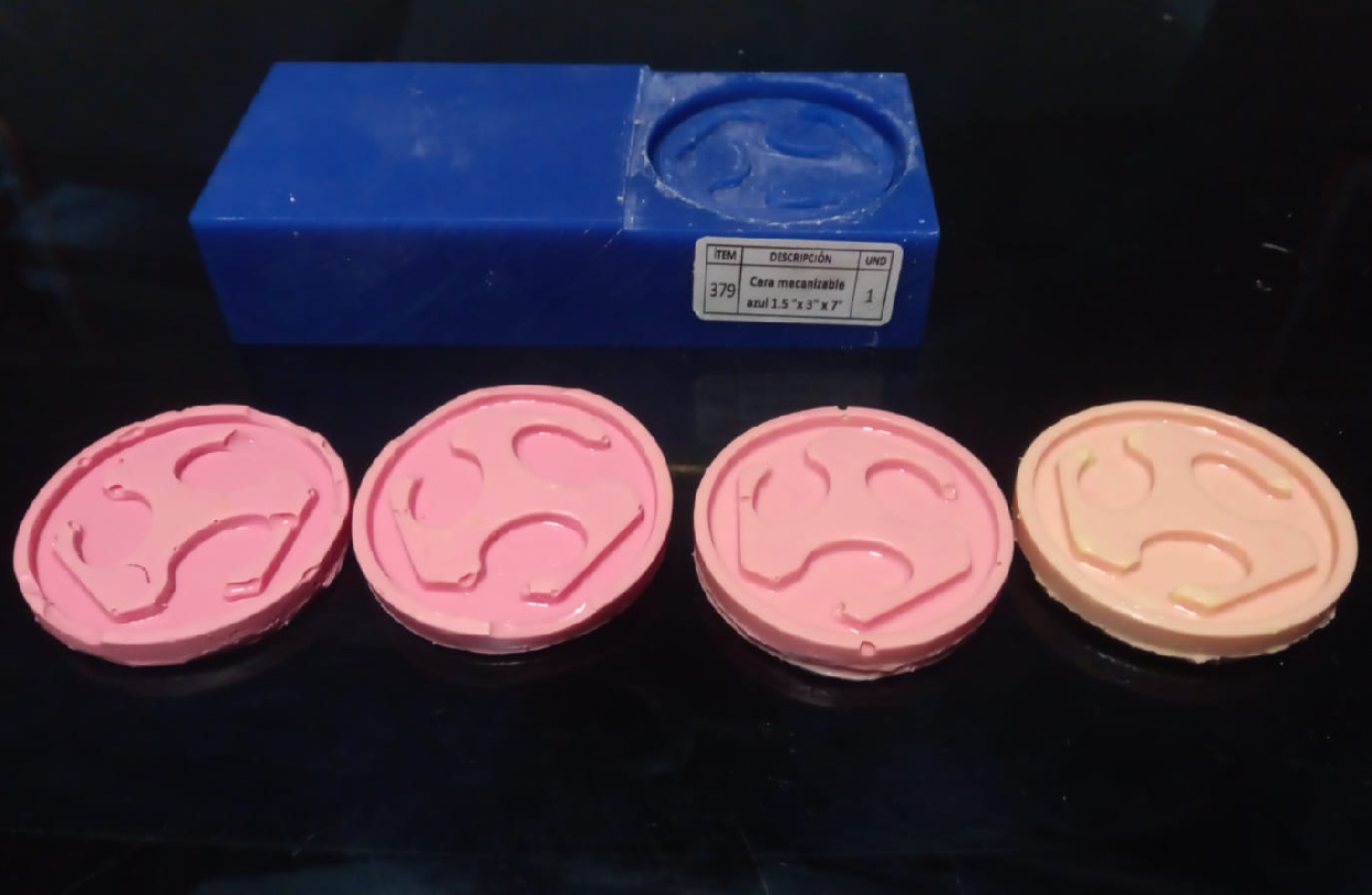
For the manufacturing of my project, I am exploring both additive and subtractive processes. Additionally, I am using a molding and casting approach, specifically designed to incorporate a custom indicator into my dispenser. This indicator will feature the FabLab logo and will be created with epoxy resin. The process begins with creating the mold using a CNC Router and wax material. Flexible resin is then poured into the mold to obtain a negative. After a short curing time, this flexible mold is used to pour the clear epoxy resin, thus creating the final product.
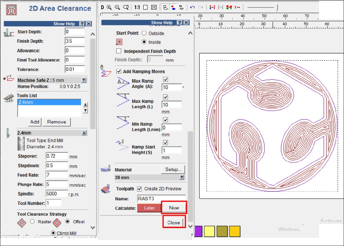
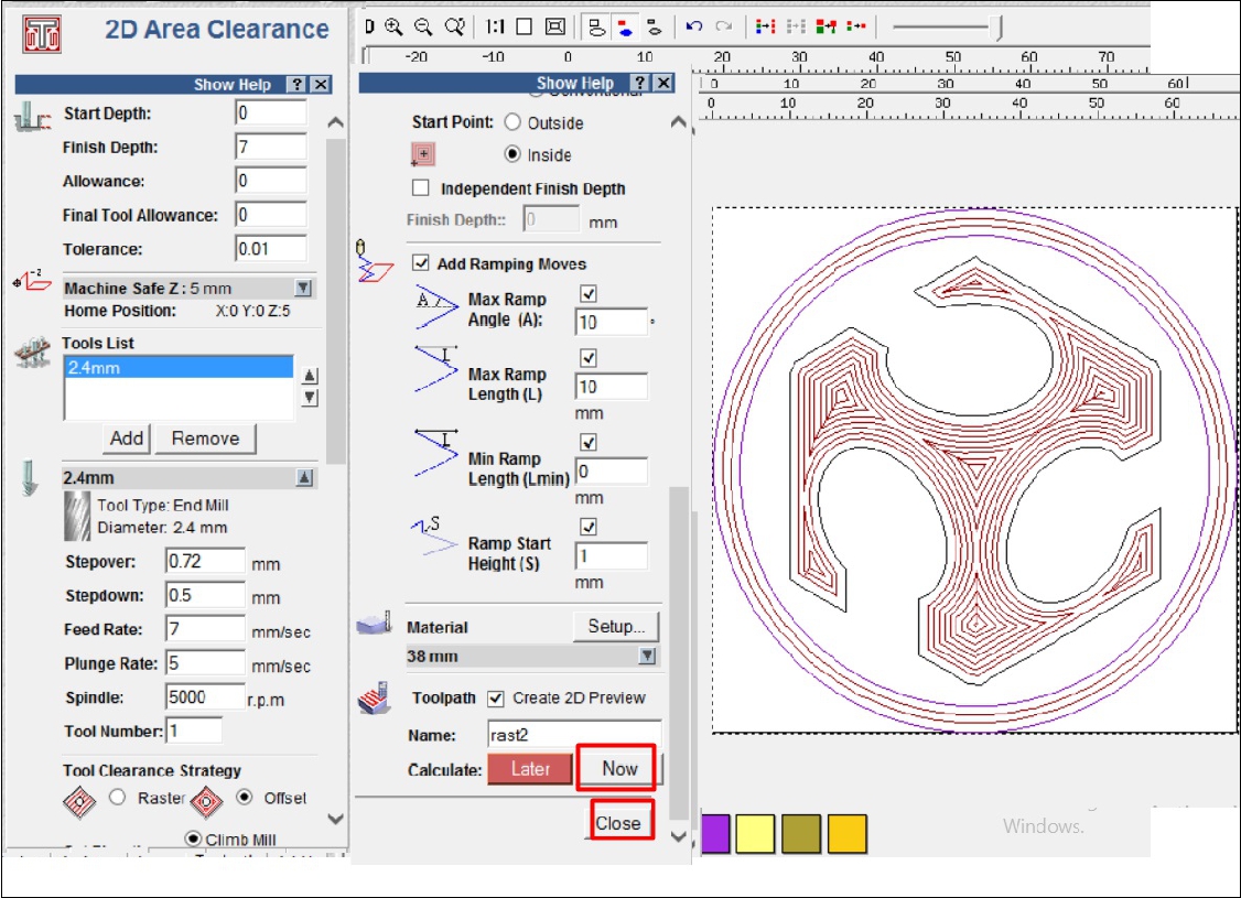
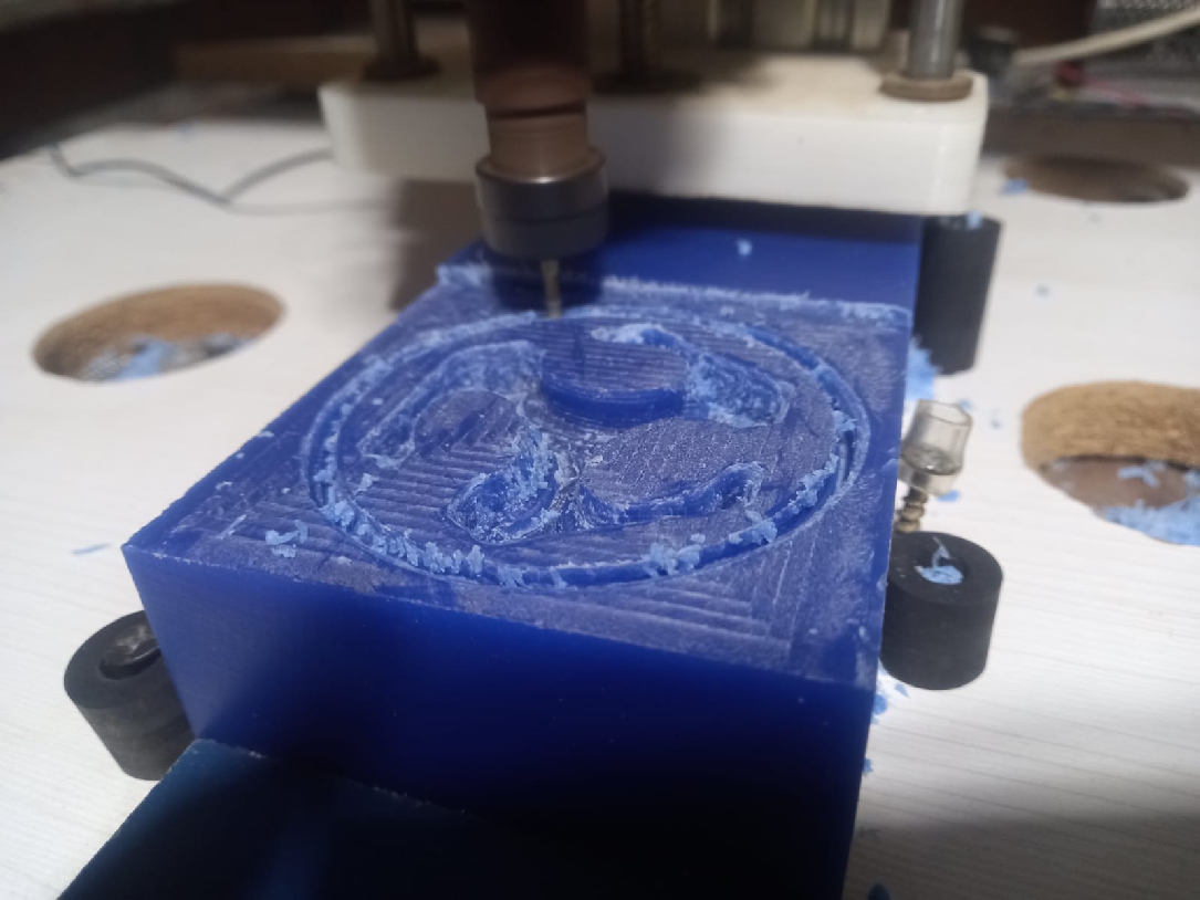
For this project, we began machining using ArtCAM software to perform roughing in three sections, as shown in the figures below.
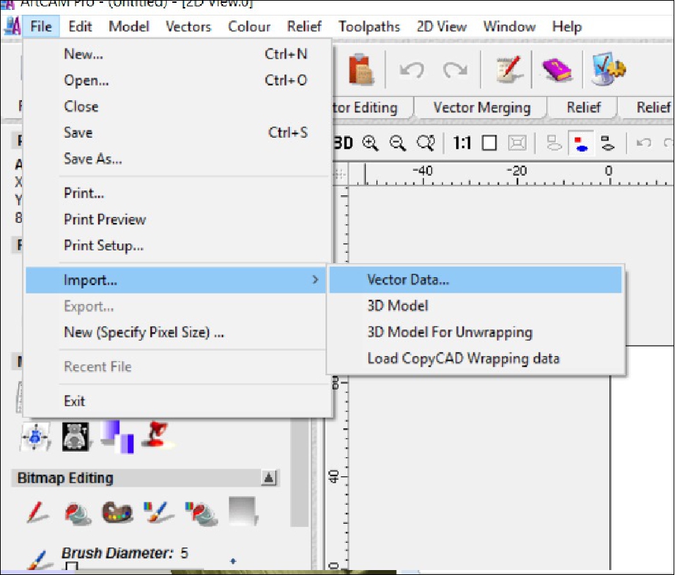
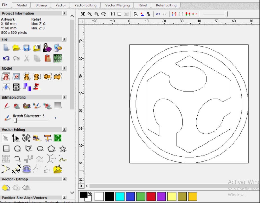
The first step was to configure the work area according to the size of the figure. Subsequently, we import the image in DXF format, as shown in the following figure. Then, we select one of the sections to carry out the roughing, as can be seen.
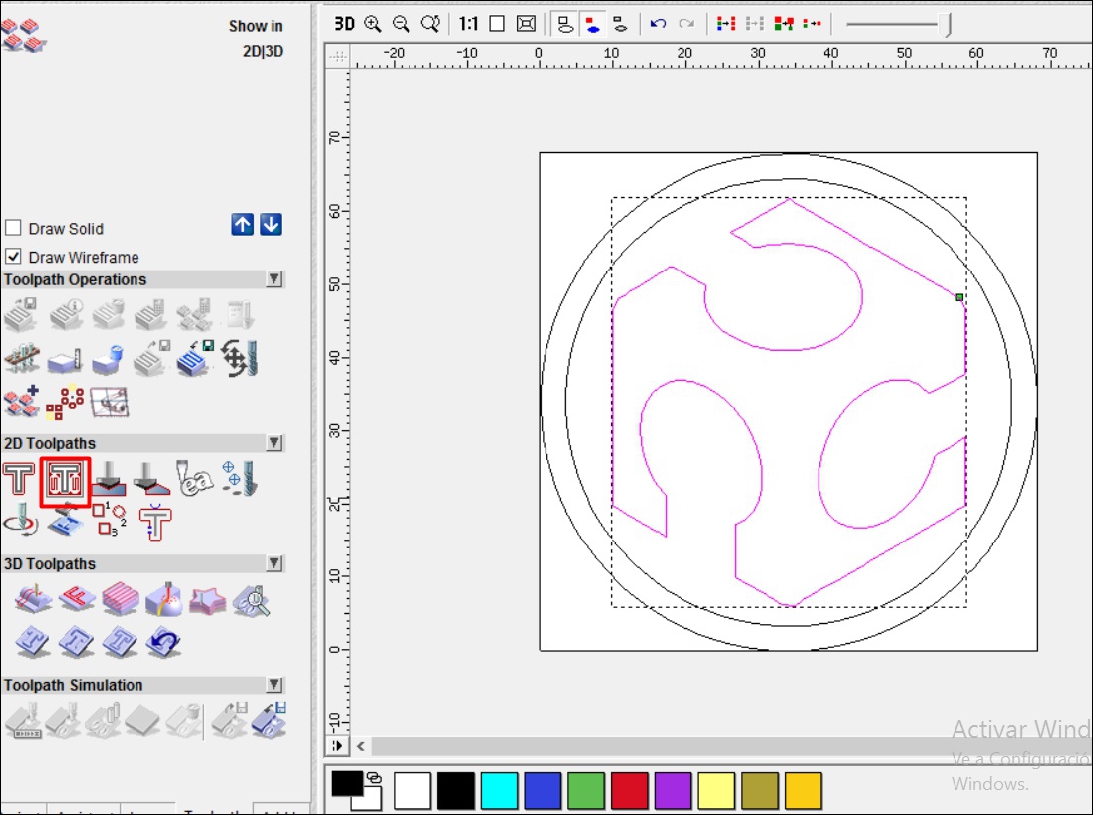
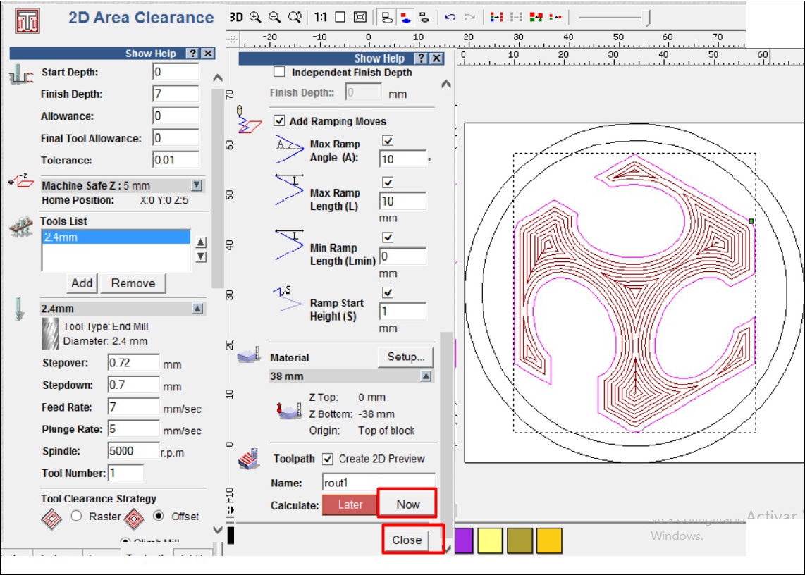
Furthermore, it is notable that the configuration of the type and size of the tool to be used was made, opting for a 2.4 mm milling cutter. In this process, detailed settings of feed rate, spindle speed and other relevant parameters were taken into account to ensure optimal machining.
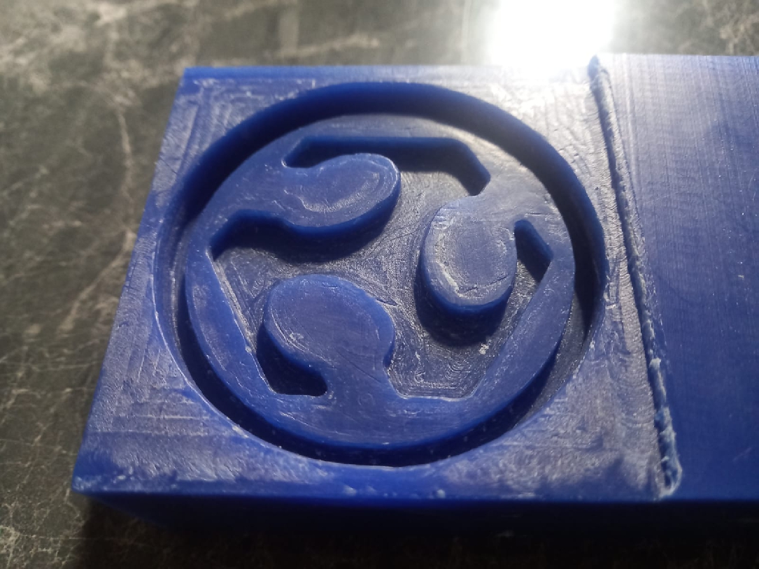
After completing the configuration, the next step involves exporting the design in G-code (millimeter) format, a crucial action to ensure that the machine can interpret the machining instructions accurately. This preparation stage is essential as it ensures effective communication between the software and the machinery, thus allowing the work process to begin smoothly.
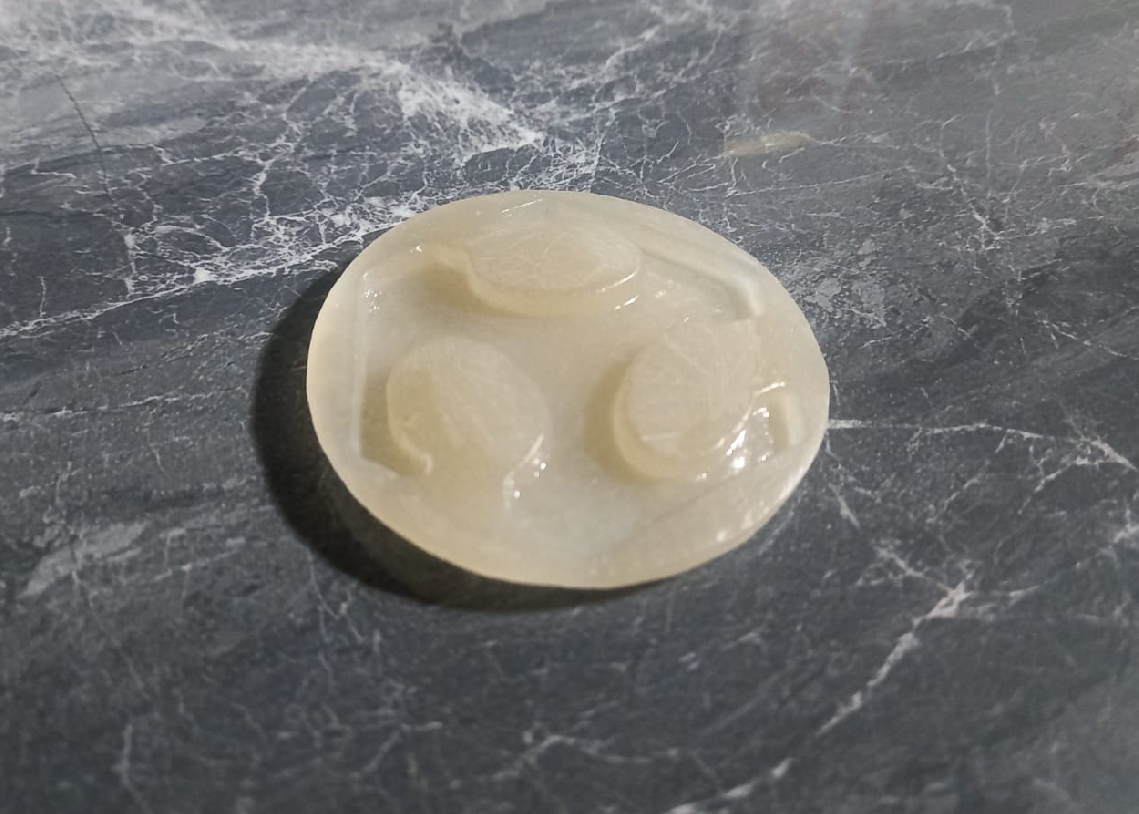
Now that the positive part mold is ready, we are ready to pour the flexible material and proceed with the replication
I'm very excited for what's coming next. The idea of being able to create my own personalized keychains, toys, and other gadgets with just a few materials is really exciting.
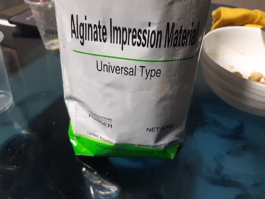
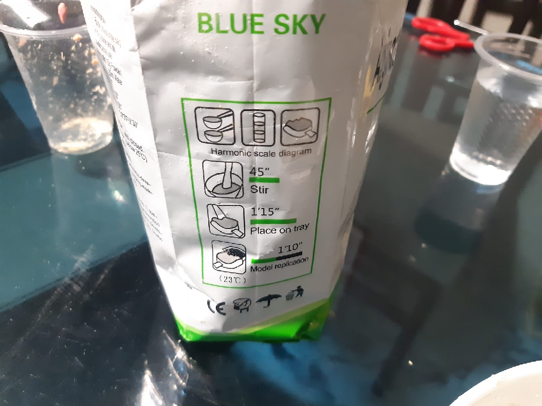
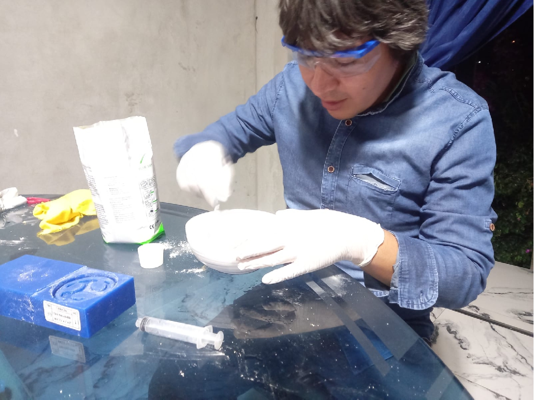
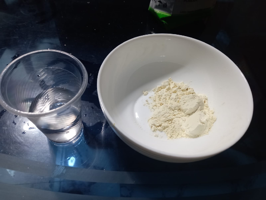
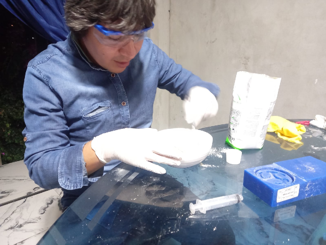
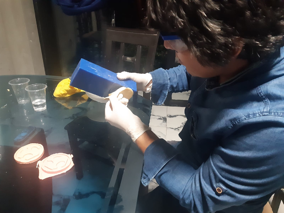
In this case, I used the alginate mentioned above, whose technical sheet was shared in the group. This material comes in powder form and, based on its specifications, requires a 1 to 1 mixing ratio as noted below along with other detailed instructions shown.
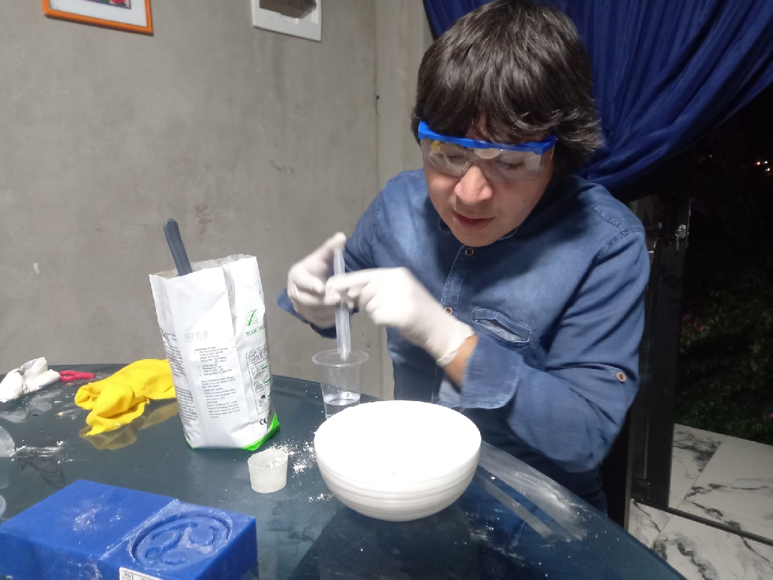
To ensure accurate measurements, I used a 15 milliliter container and a 10 milliliter syringe to calculate the exact amount of alginate and water needed, following the instructions on the data sheet. In this case, 45 grams of alginate and 45 milliliters of water were used, as specified.

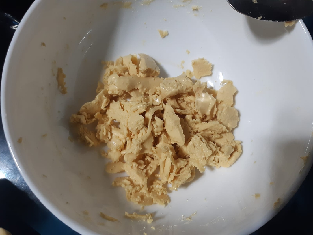
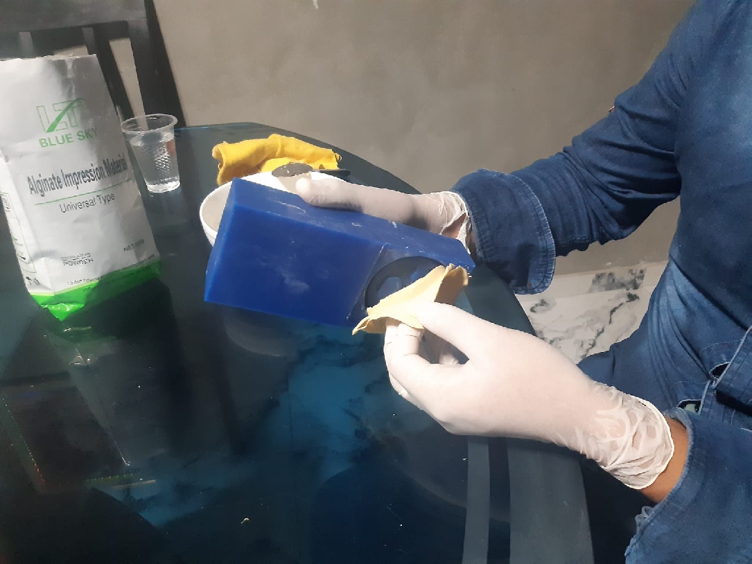
It was a big surprise to discover that, according to the data sheet, the estimated processing time was approximately 10 to 30 minutes. However, in just 30 seconds, the material dried completely, as can be seen in the following image. Due to this unexpected situation, I had to perform a new calculation and adjust the process
Taking the previous test as a reference, the next step was to add more water, in this case, 60 milliliters, that is, 15 milliliters more than what the product's technical sheet indicates.
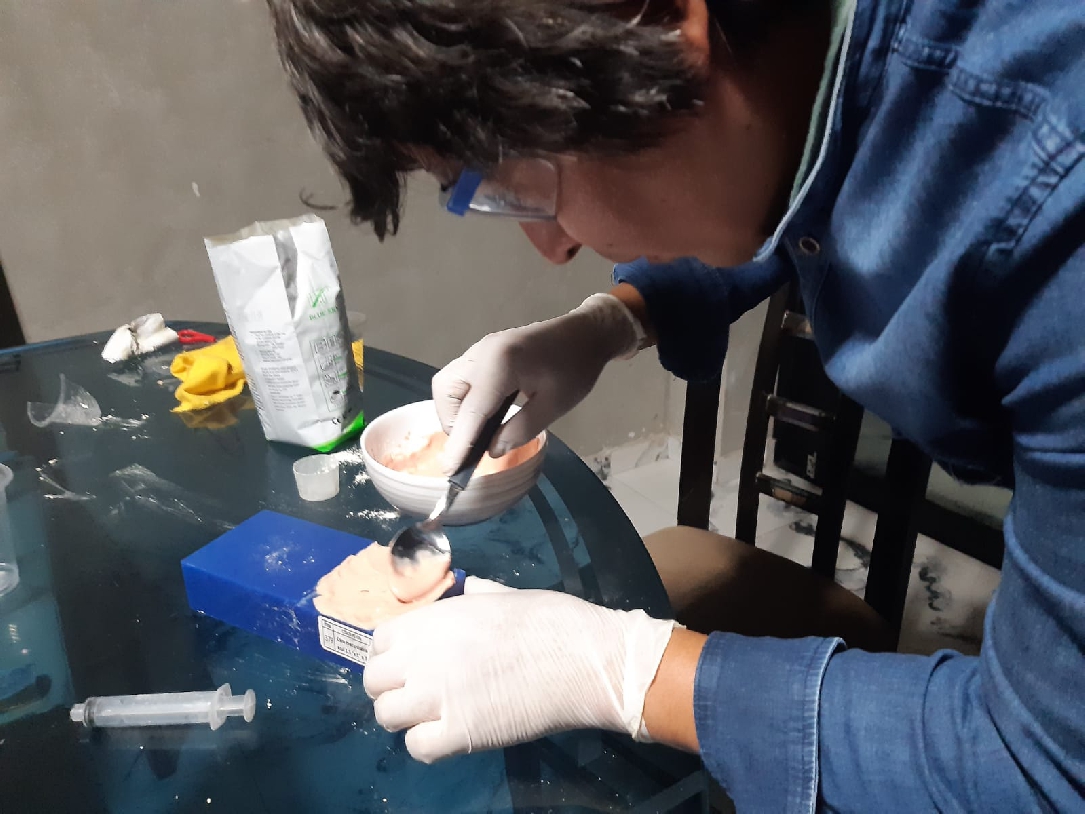
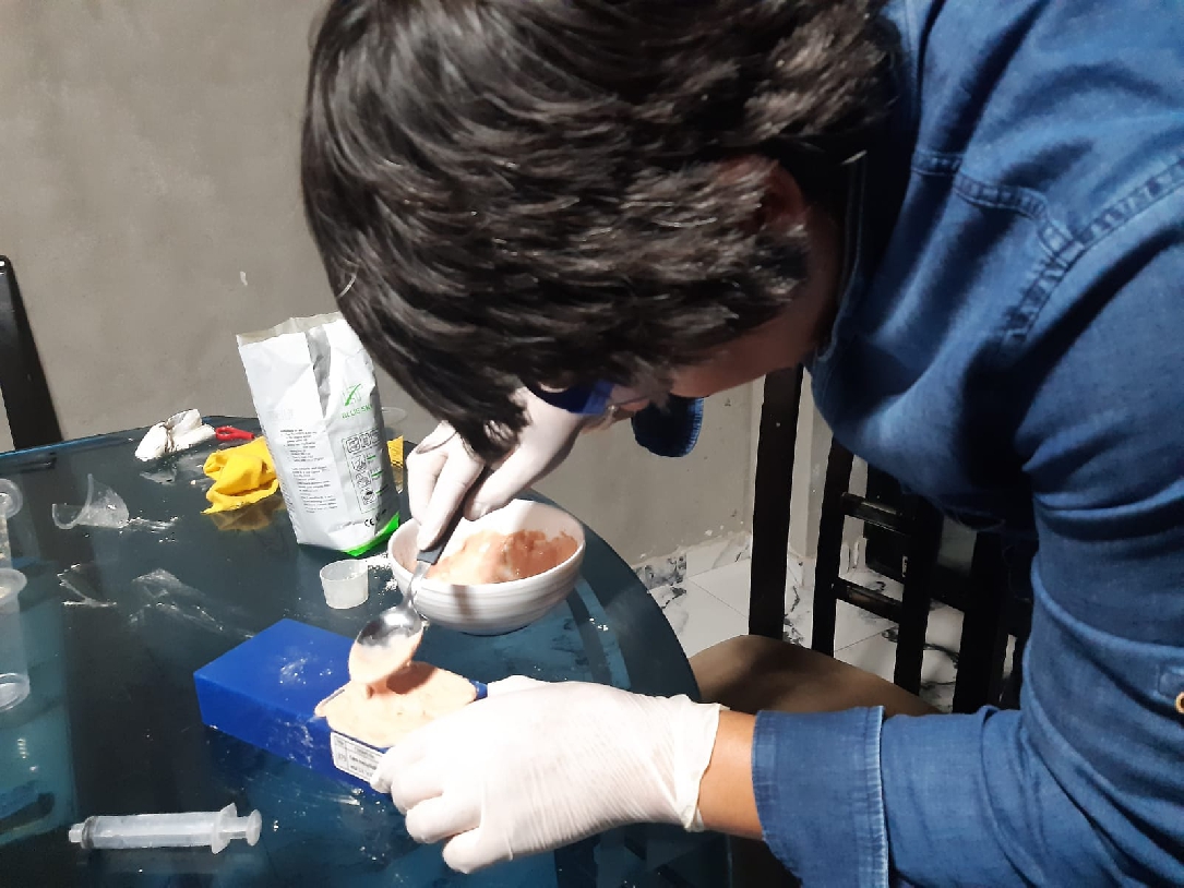
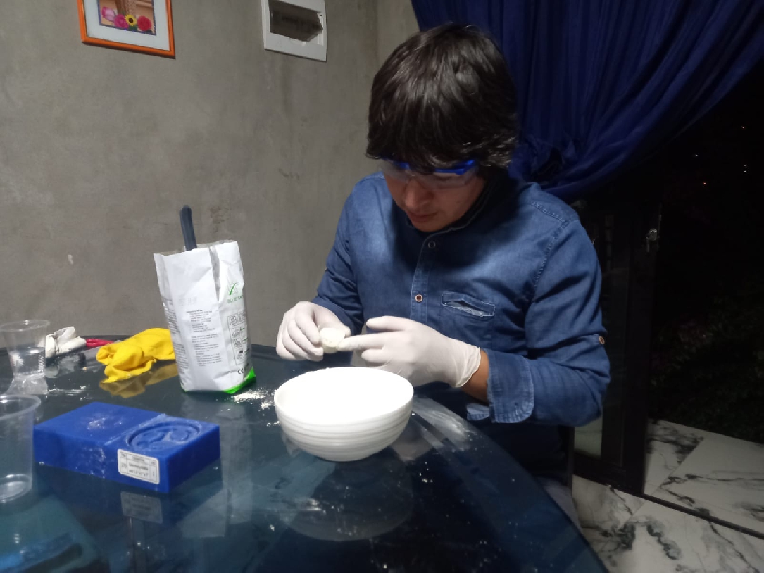
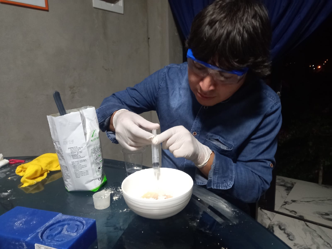
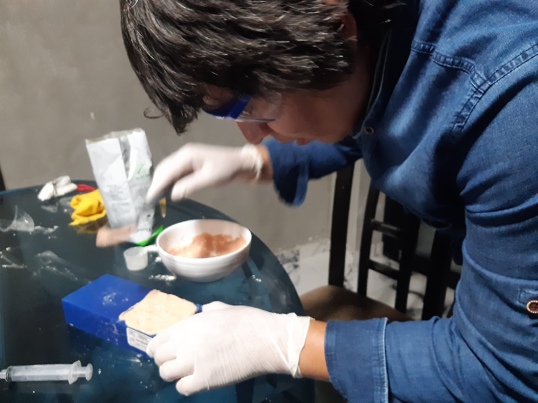
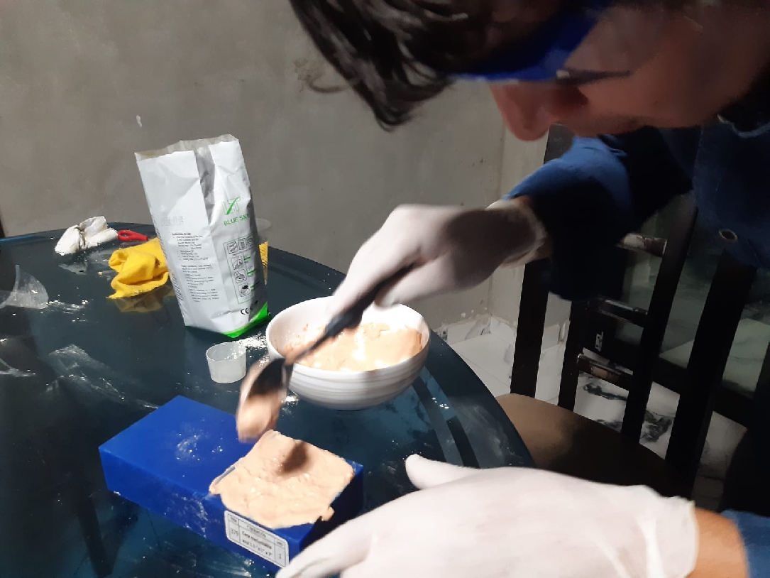
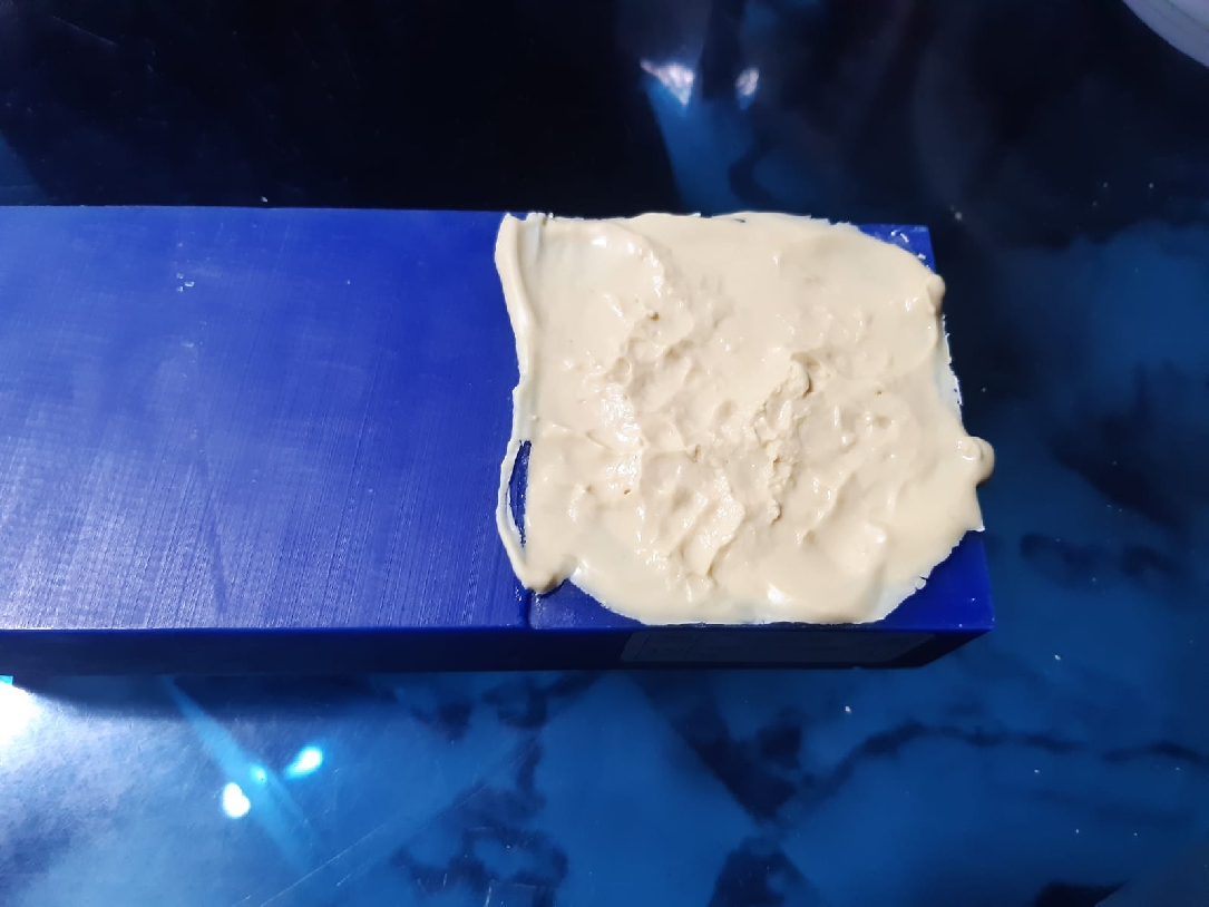
Although the process was quick, I had to repeat it 4 times due to the presence of bubbles. In the first three operations, the bubbles persisted. In the first one, I poured it with a spoon, while in the next two, it took me too long to pour it into the mold. However, in the fourth operation, drawing on previous experience, I simply poured the material and allowed all the holes to be filled evenly by gravity.
The drying process takes approximately 17 minutes, although this time may vary depending on environmental conditions. It is important to note that once the material is solidified, it can be removed carefully to avoid damaging it.
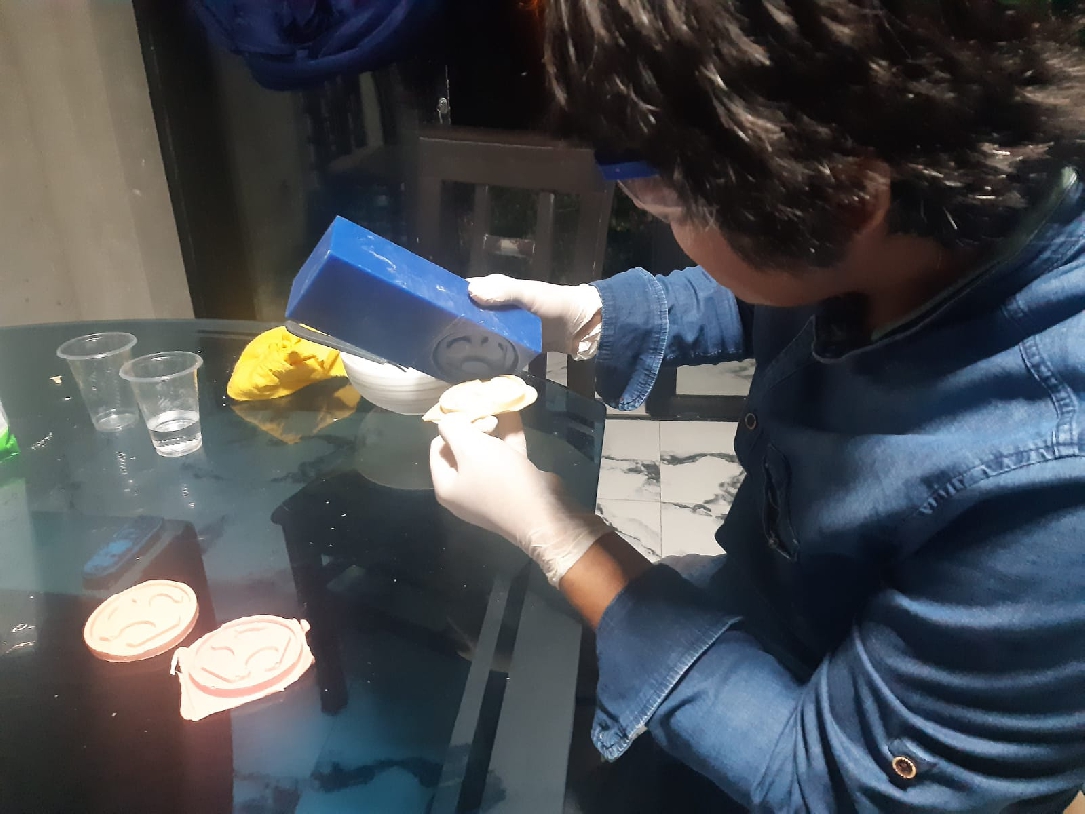
In the following image you can see the results of the four attempts, with the final acceptable product being the fourth one, where I managed to obtain the desired result.
After waiting only 17 minutes, the product is ready. It is surprising how fast and effective this process is. Now we can start making replicas and have your toys personalized with these products. It's exciting to see our ideas come to life so quickly and effectively!
The electronic design was carried out using KiCad software. The first step was to make a list of all the necessary components. Then, the electrical schematic was designed and the layout of the components on the schematic diagram was organized meticulously.
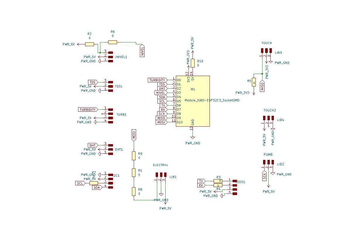
For PCB design, it is important to consider the layout of components in terms of distance and orientation. Additionally, it is crucial to determine the width of the tracks; in my case the width used is 0.8 to 1 mm.
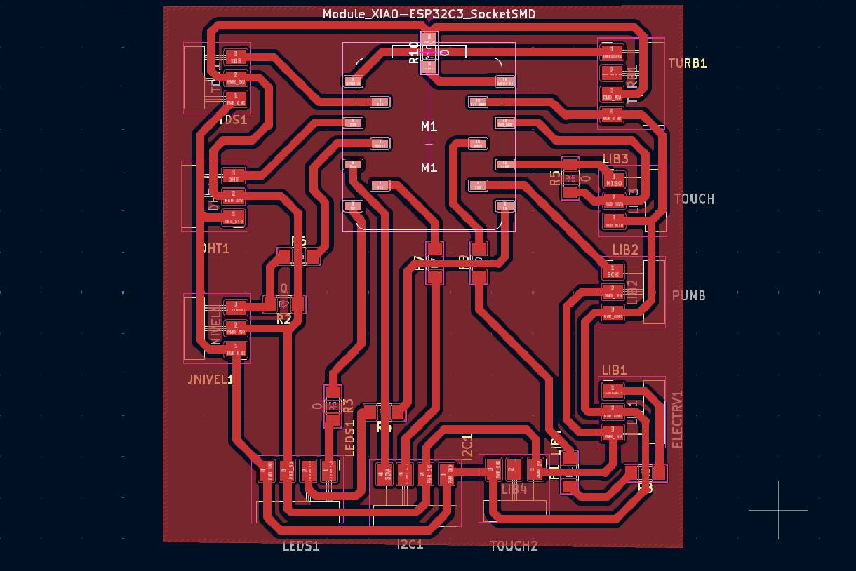
In this process, it is possible to visualize how our board will look in reality, since it is designed on a real scale. Additionally, a 3D view of the board can be generated to obtain a more detailed representation of the final design.
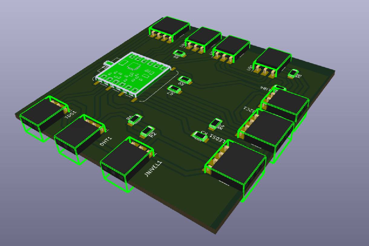
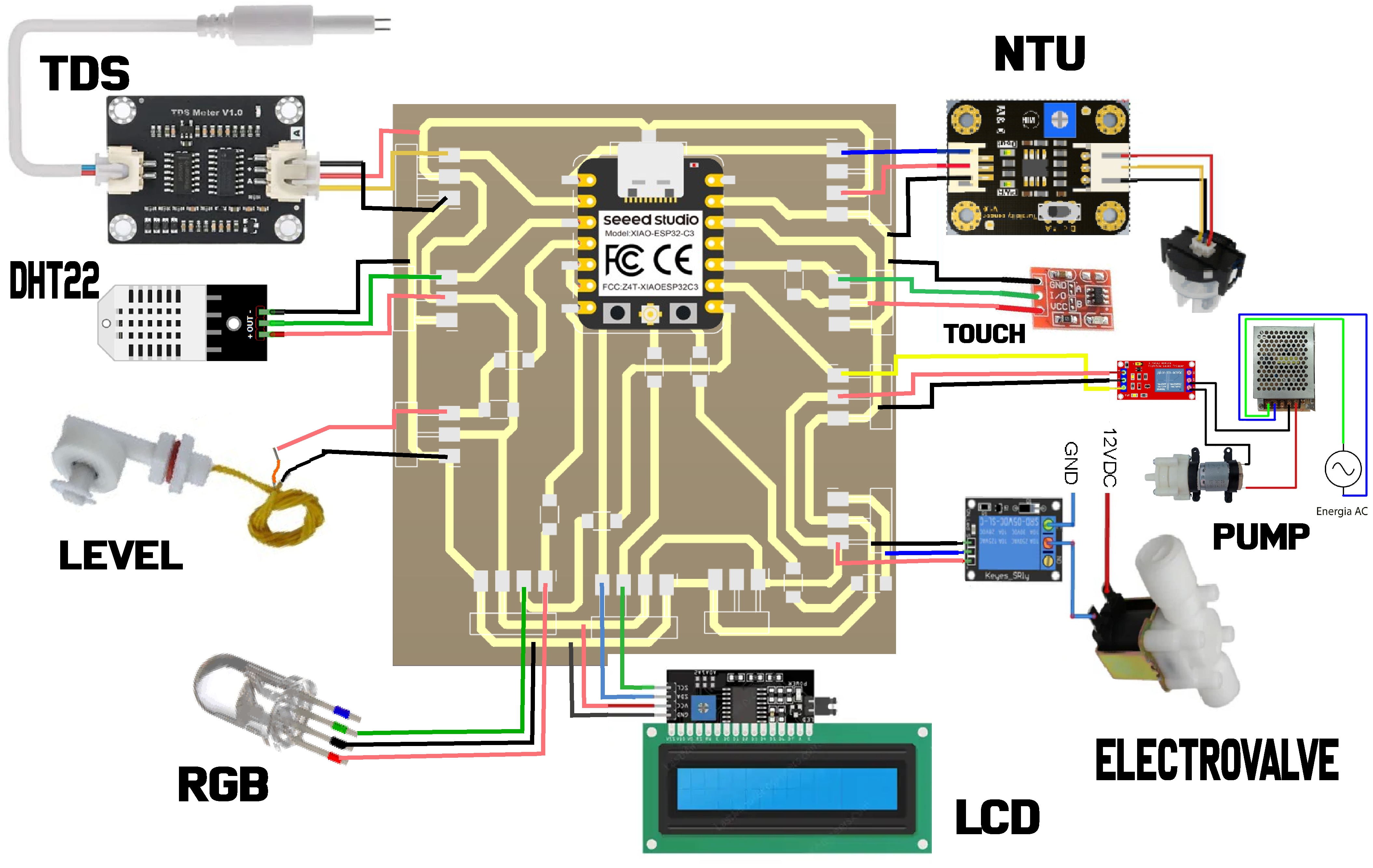
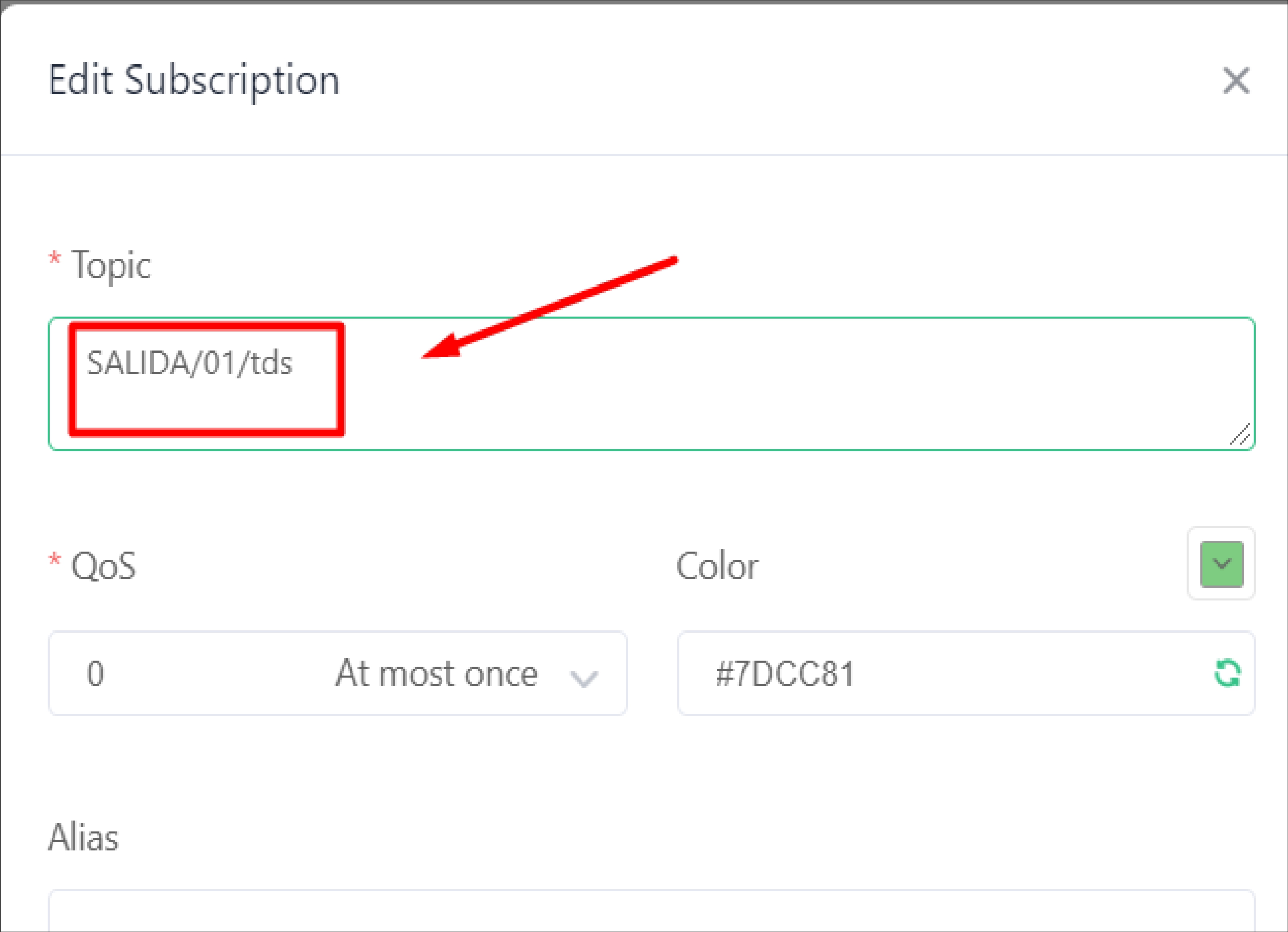
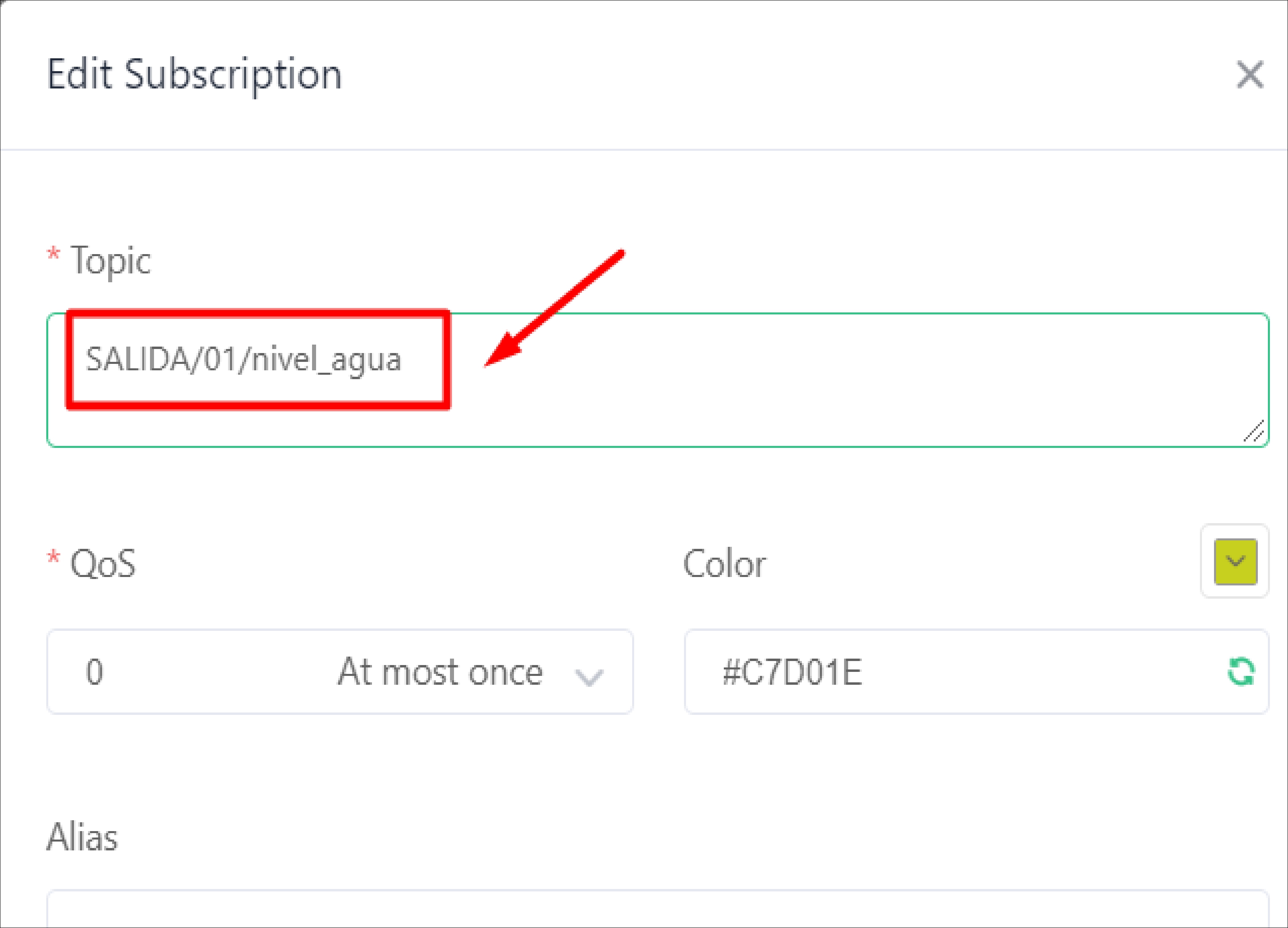
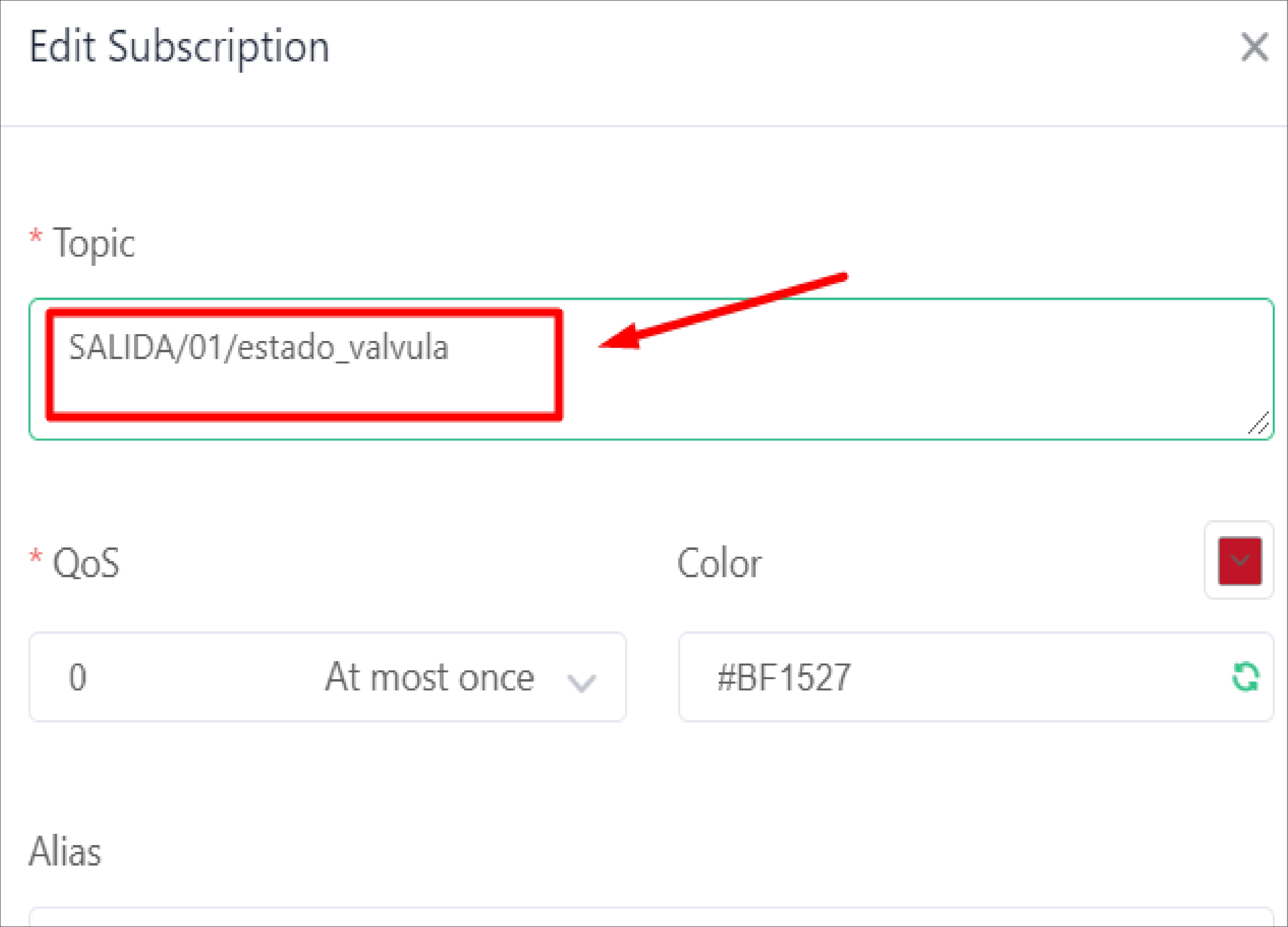
In the following image you can see a better distribution of components for this design and thus have a clearer vision of what our board will be like, with the inclusion of sensors (TDS, turbidity, level, DHT22, capacitive touch) integrated into the board, as well as the actuators, such as the solenoid valve and the mini peristaltic pump, as well as the relay modules.
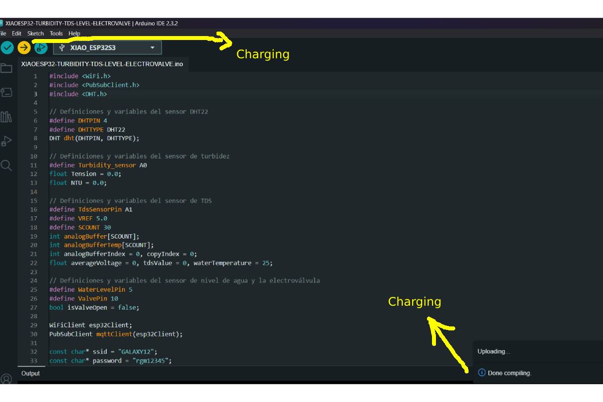
To carry out the readings and operation tests, I used the Arduino IDE with the XIAO ESP32-C3. In the development, I included the necessary libraries for the sensors and components of the project, such as WiFi, PubSubClient and DHT. These libraries are essential for the operation of sensors such as DHT22, turbidity, TDS, level, and other components necessary for the project.
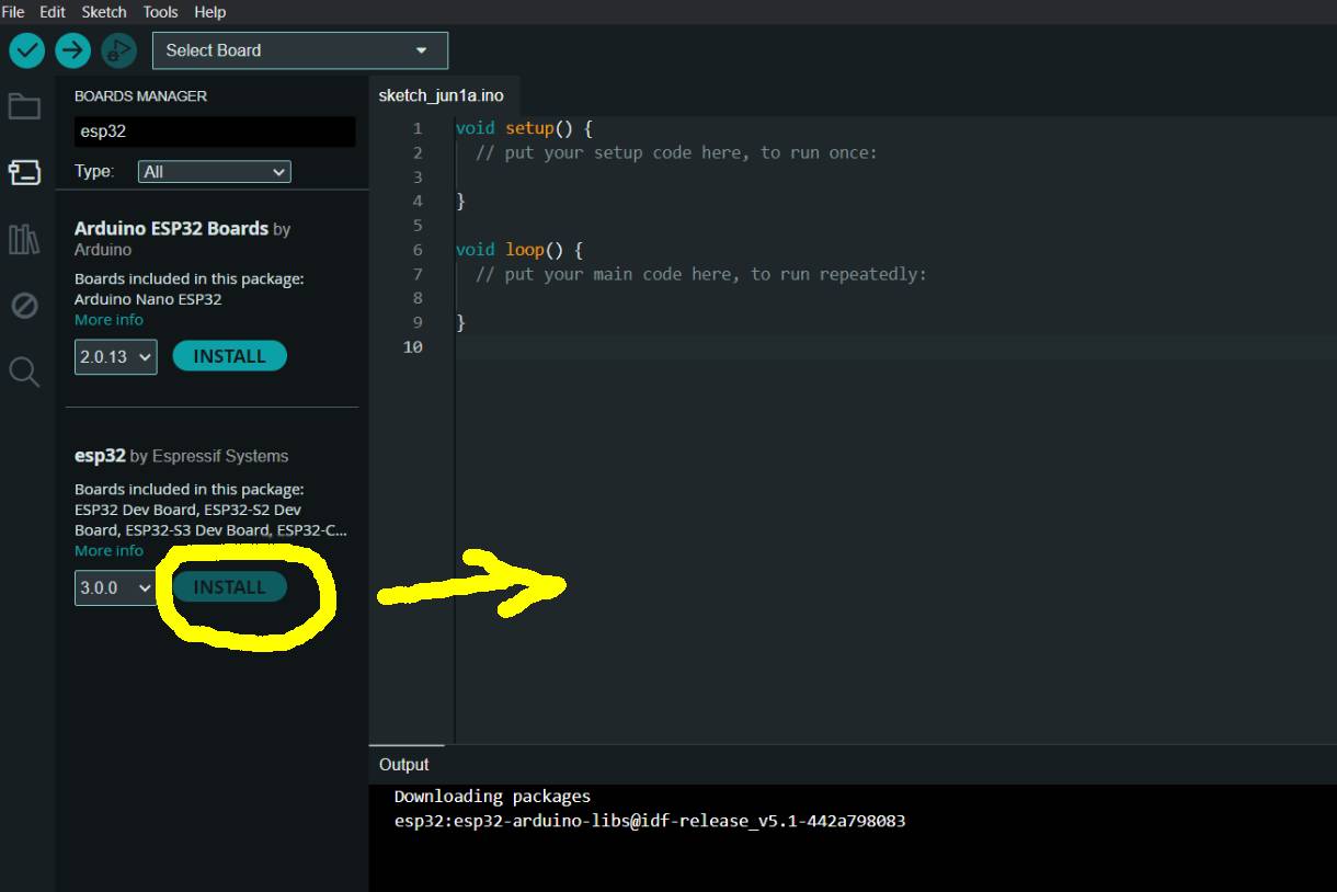
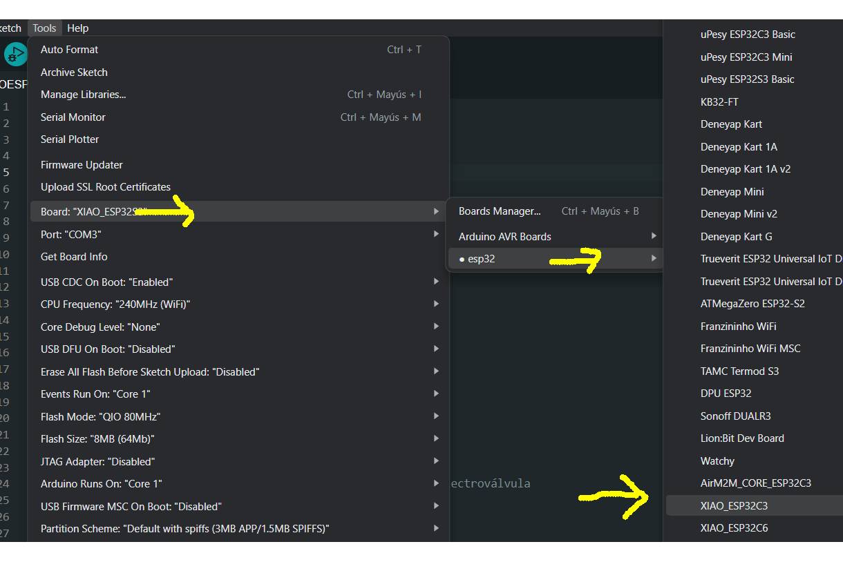
For installation, it is important to identify which is the appropriate package for our board. In my case, I installed the esp32 by Espressif Systems package. Next, I selected the XIAO ESP32-C3 board, as you can see in the following images.
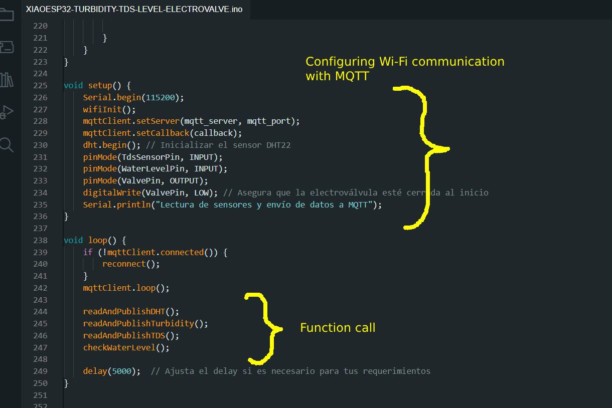
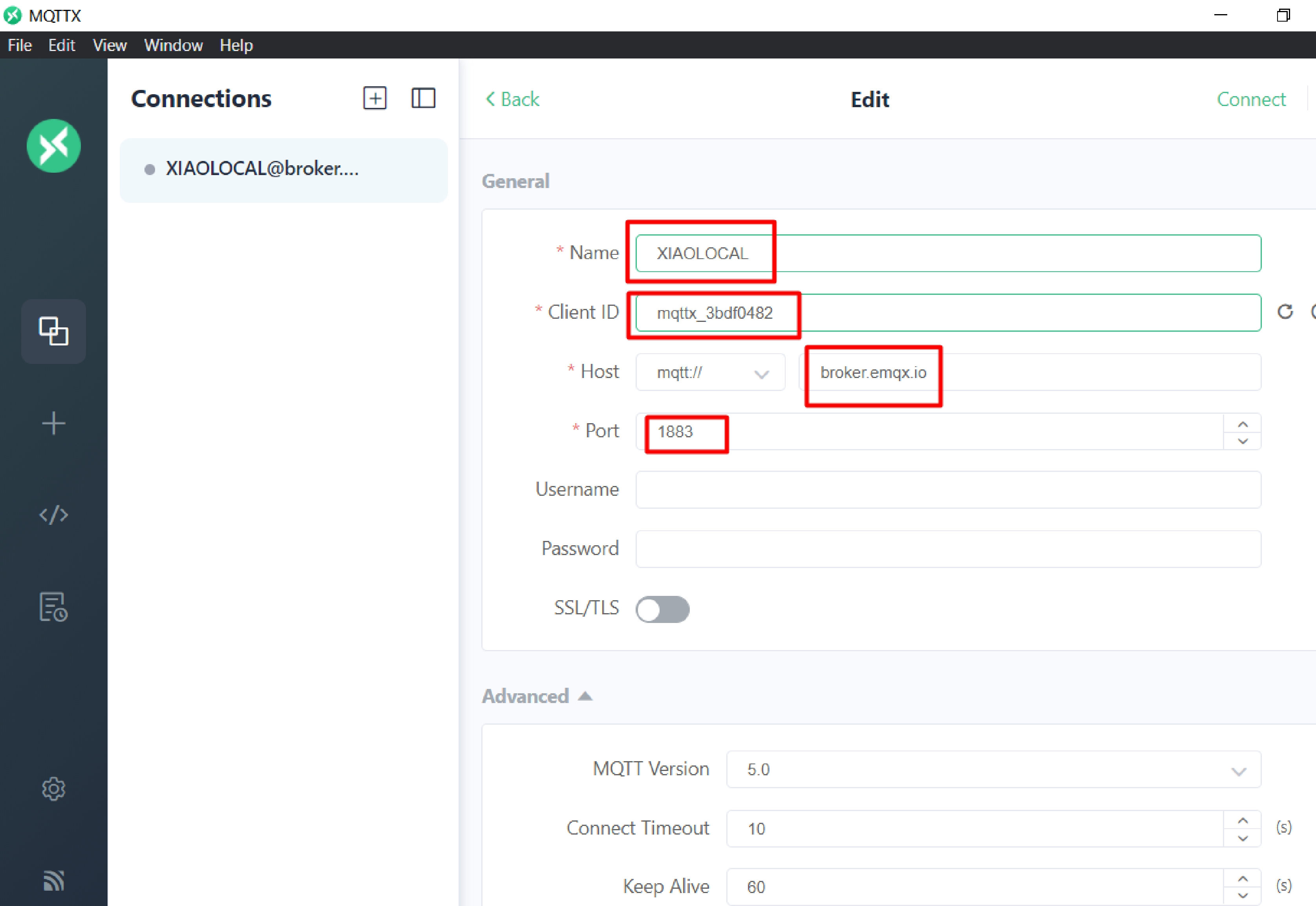
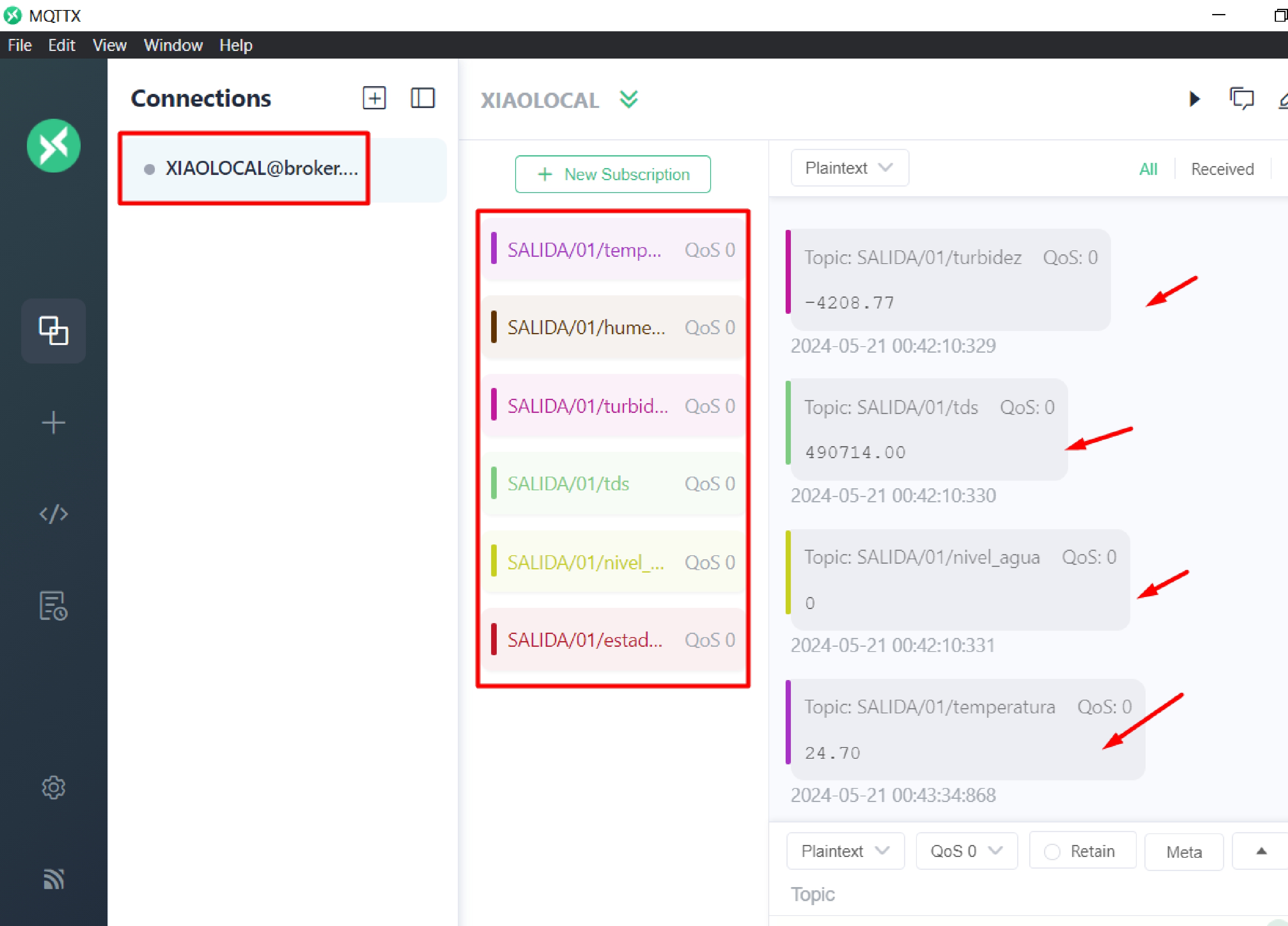
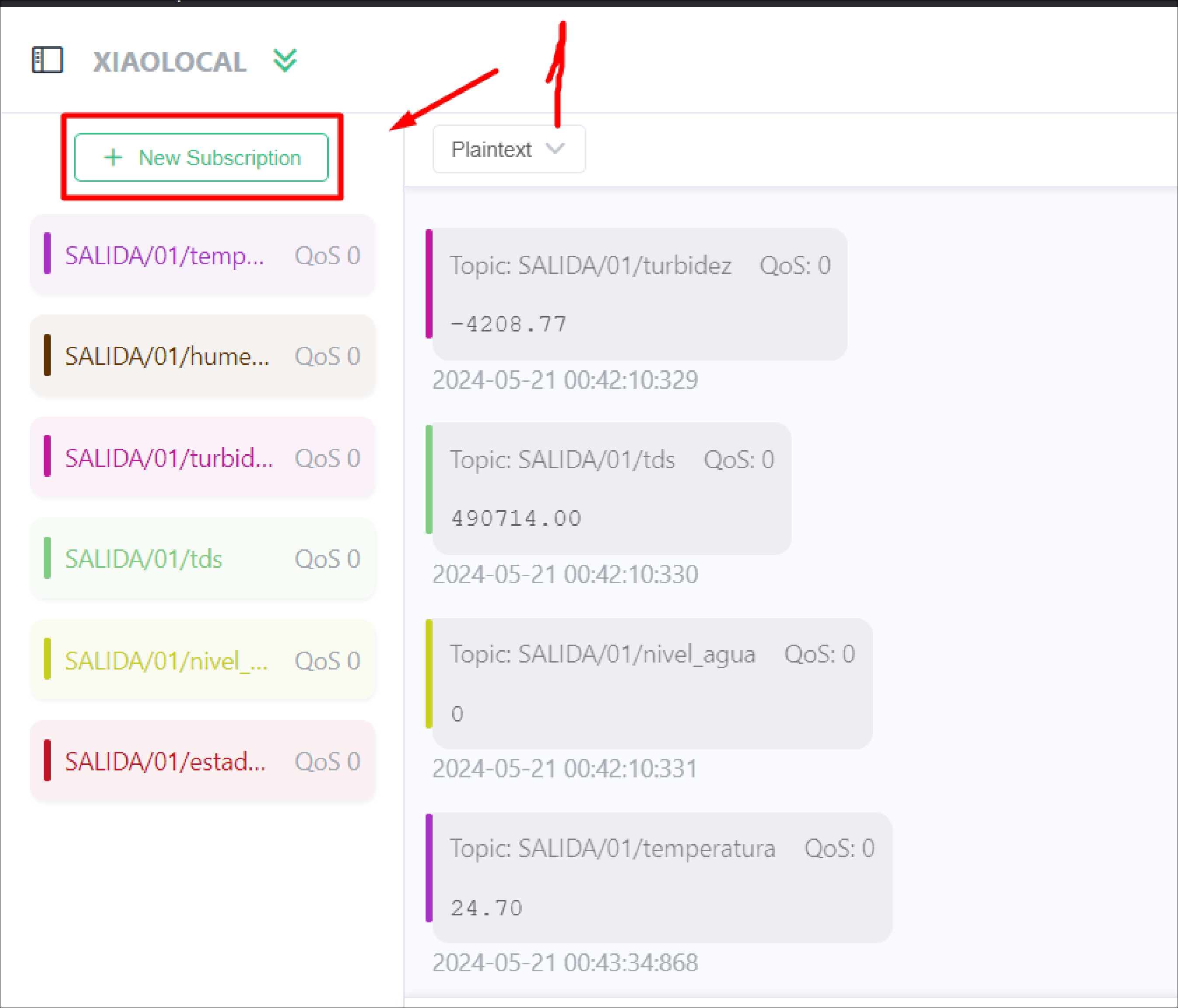
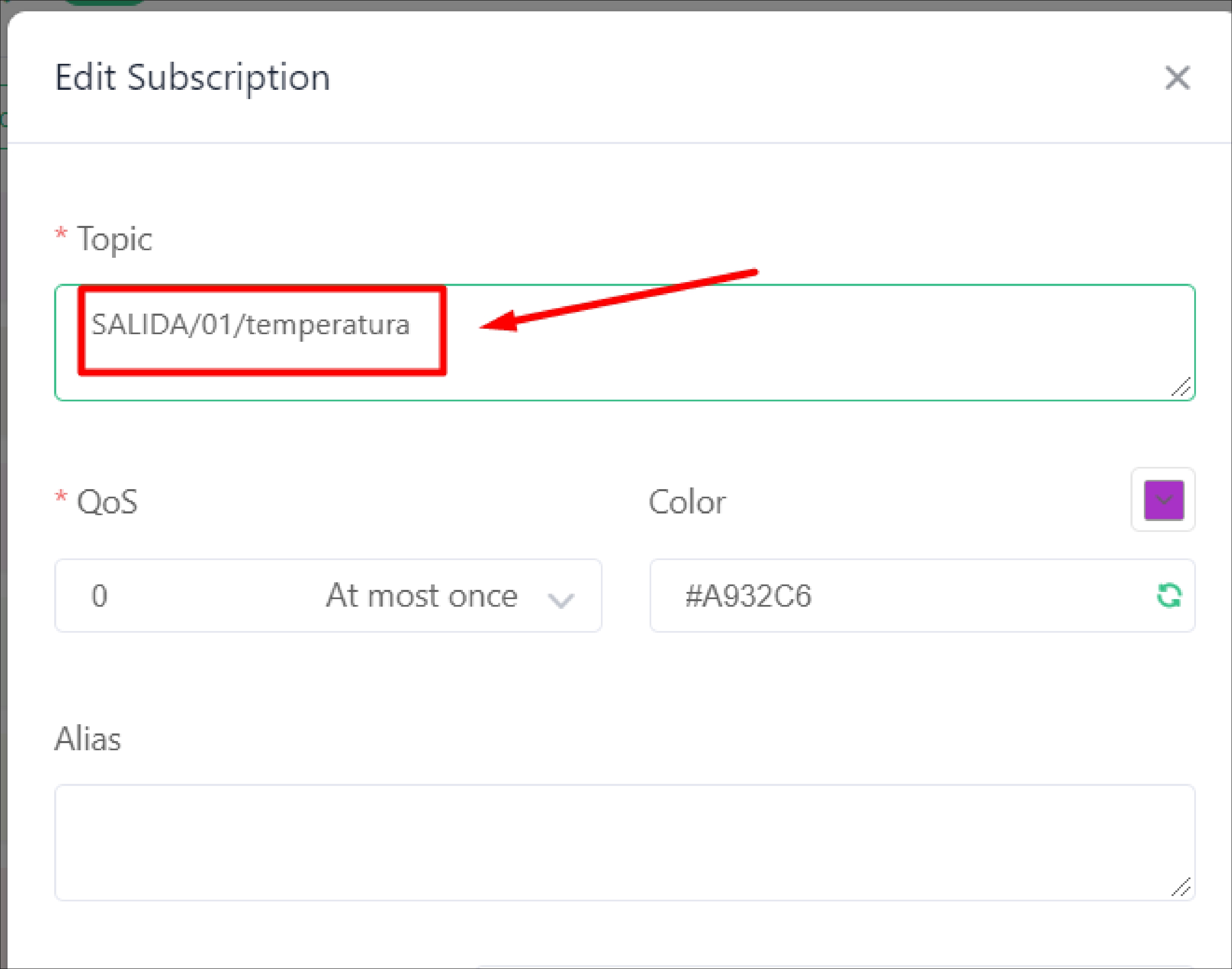
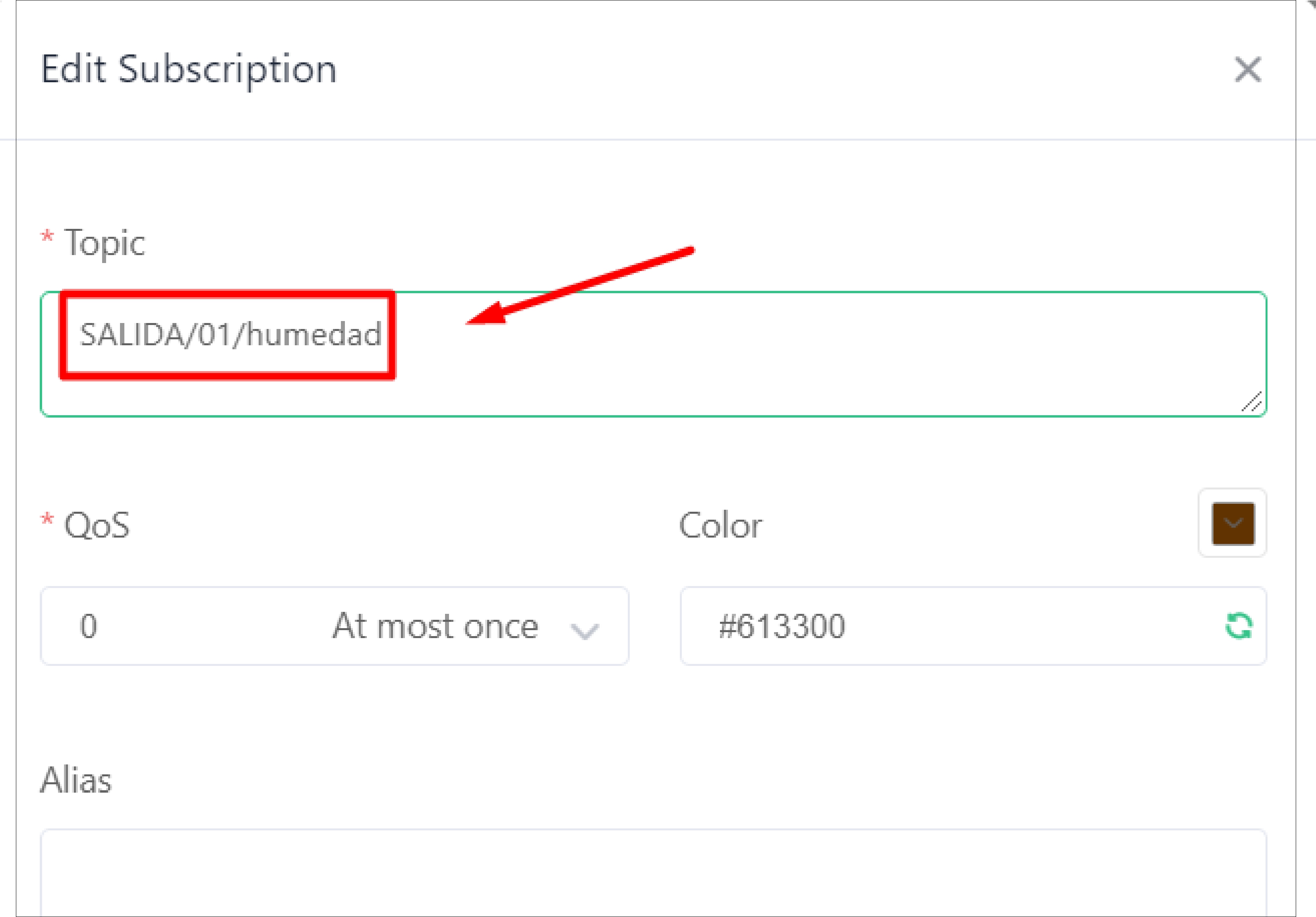
In the following image you can see the source code where it is seen that the sensor readings are being taken and sent in real time through MQTT using WiFi. Subsequently, the charging process can be displayed on the XIAO ESP32-C3 board.
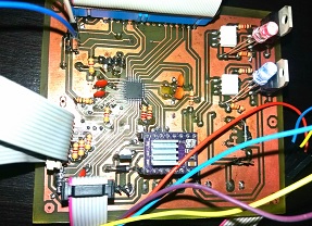
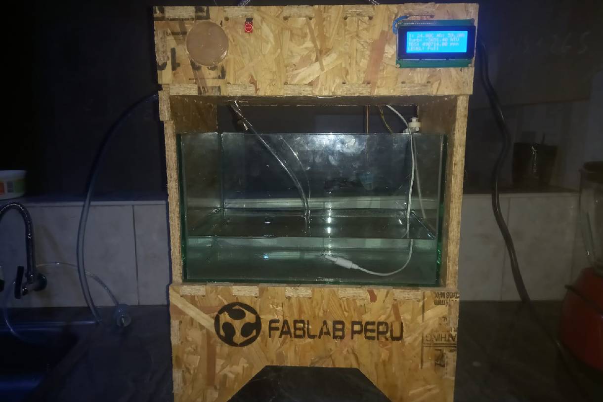
The following images show the first tests of the project, where the ignition and operation of the pump that feeds the tap can be seen.
This week has been essential to advance the completion of my final project. These last weeks are dedicated to completing the final project, and I am noticing how we are incorporating more processes than we had initially considered. It has been an exciting challenge and very rewarding to see how the project evolves.
Development of custom electronic boards with CNC Router.
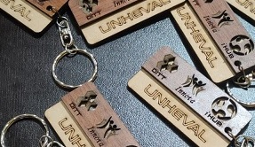
Development of personalized keychains and ornaments with CNC Laser.
Development of custom machines "Desktop CNC Laser.

Huánuco is a Peruvian city, capital of the district, province and department of the same name in the north-central area of the country. The city has a population of 235,529 inhabitants. .